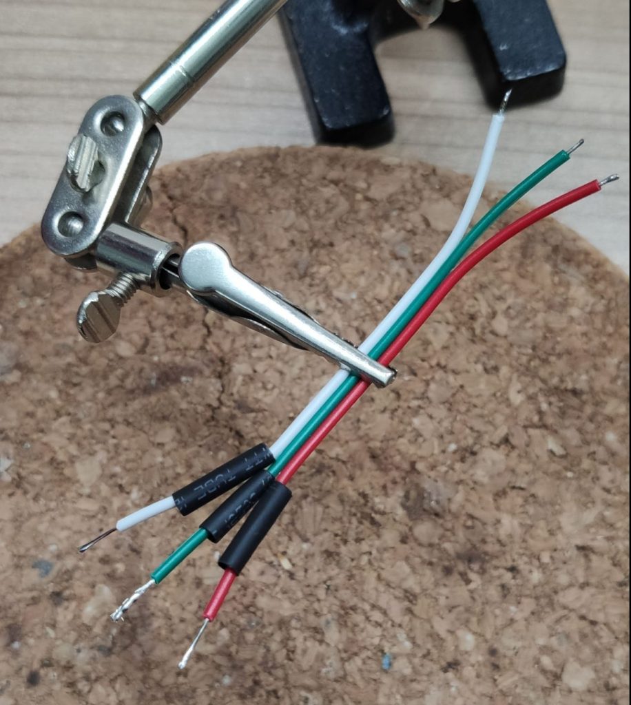
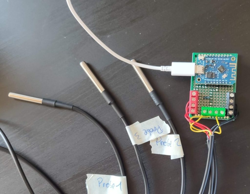
Recently I found some nice Dallas temperature sensors on AliExpress. These sensors came with a metal probe enclosure and one meter wires attached to it. I ordered some without a special reason just have them around. Couple days later I watched a YouTube video from Sir GoodEnough where he added such sensors to his cottage heating system. That inspires me to add these sensors to my central heating as well 🙃.
The Idea
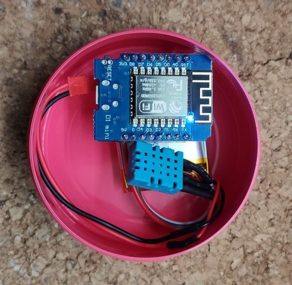
To monitor the temperature of my central heating unit I wanted to place four sensors to the system. One at the hot water tank and three to the heating system itself. All sensors must be attached outside the water system. That way the system stays untouched and I don’t have to be afraid about leaks, etc. All sensors are linked together on a perfboard which also houses a D1 Mini that runs ESPHome to get all the data into Home Assistant. This is a similar design as in my DIY Yardbell project.
Parts list
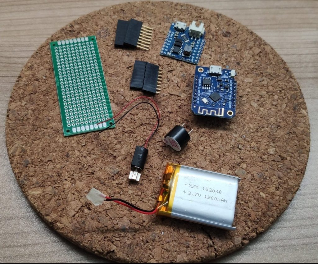
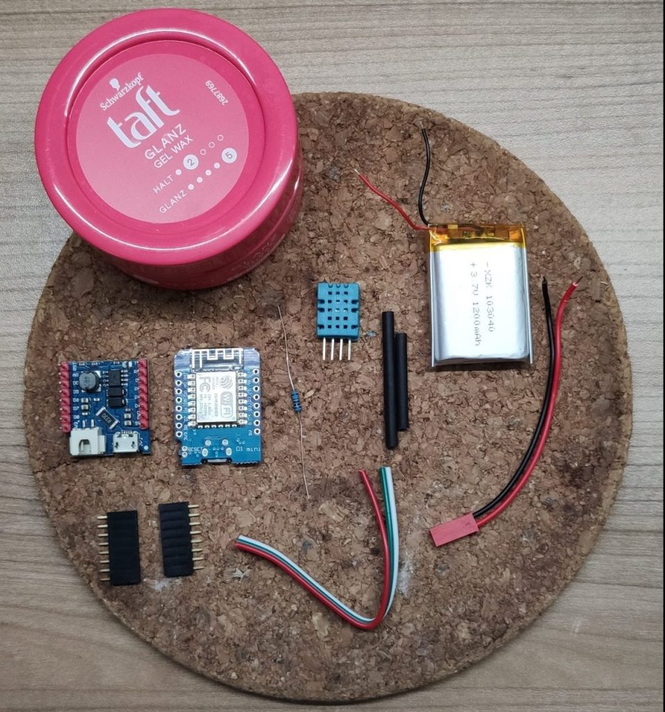
For the DIY heating monitor we will use the following components:
- Dallas temperature sensors
- 1x small perfboard 4x6cm
- 1x 1KΩ resistor
- Screw terminals in various colors
- 1x D1 Mini (including pins and female connectors)
- 1x 5V USB phone charger
- 1x micro USB cable (might differ if you’re using the latest D1 Mini with USB-C)
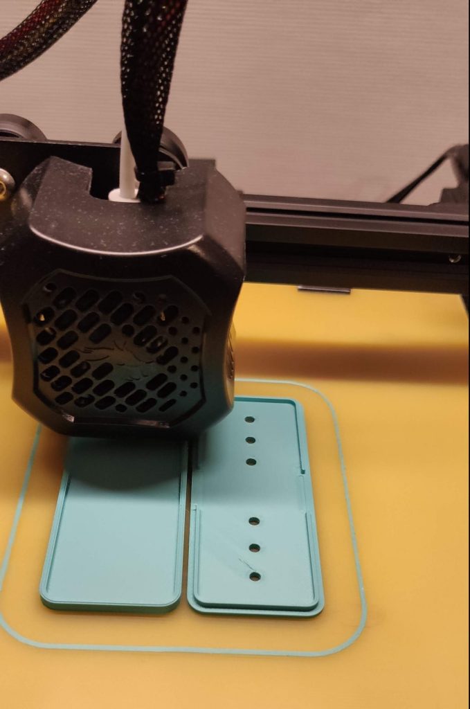
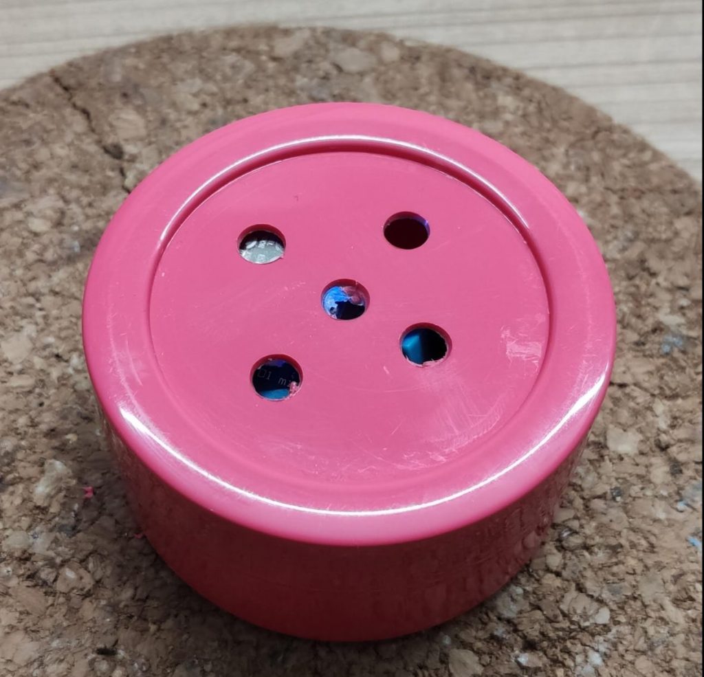
- Optional an enclosure for the perfboard (I used a electrical box)
- Stuff to mount the probe (zip ties, tape, isolation foam)
*Some links are affiliate links. If you use them to buy the parts for your project you will help me and my next project. These links will cause no extra fees or costs to you

Let’s Go!
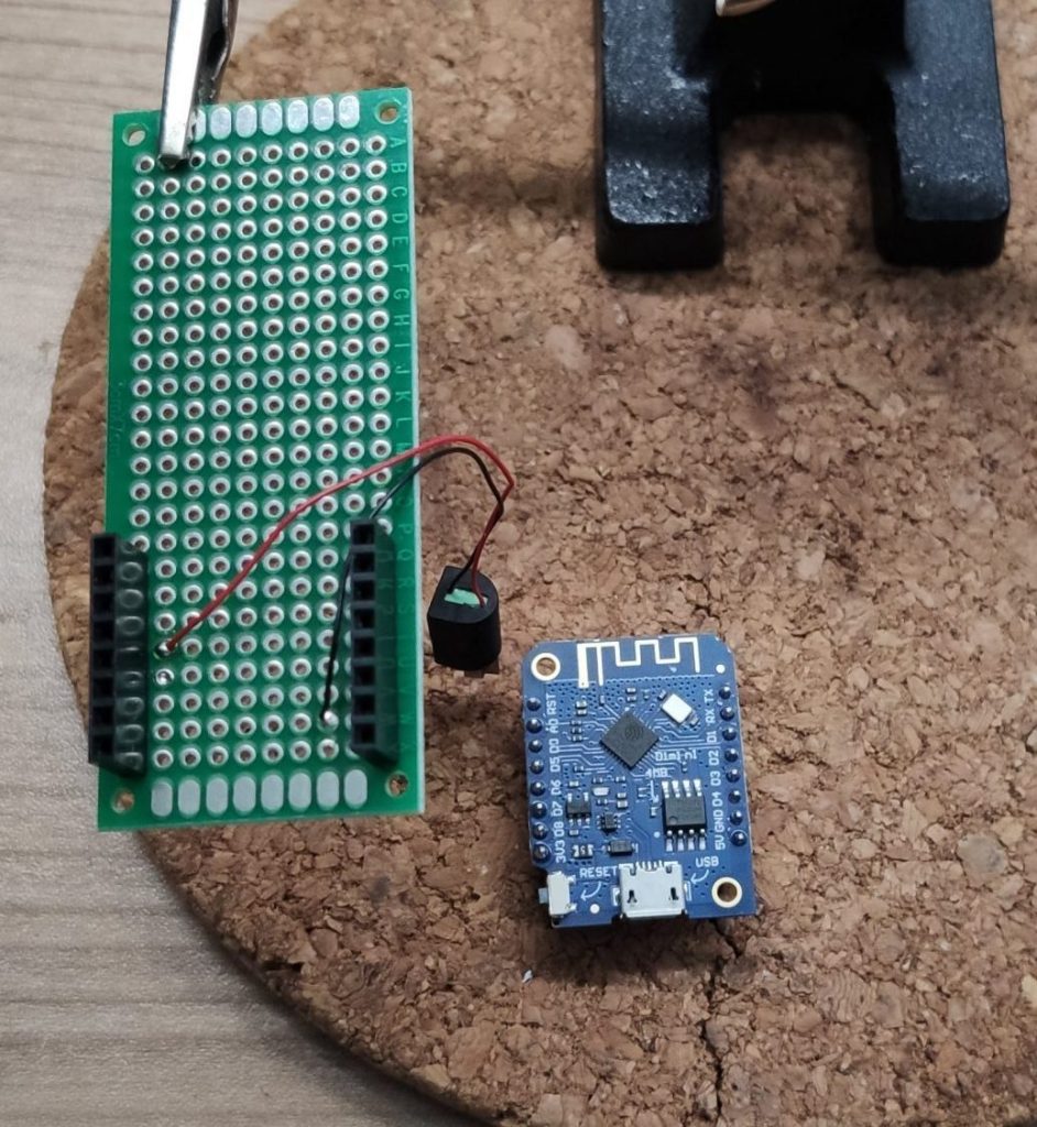
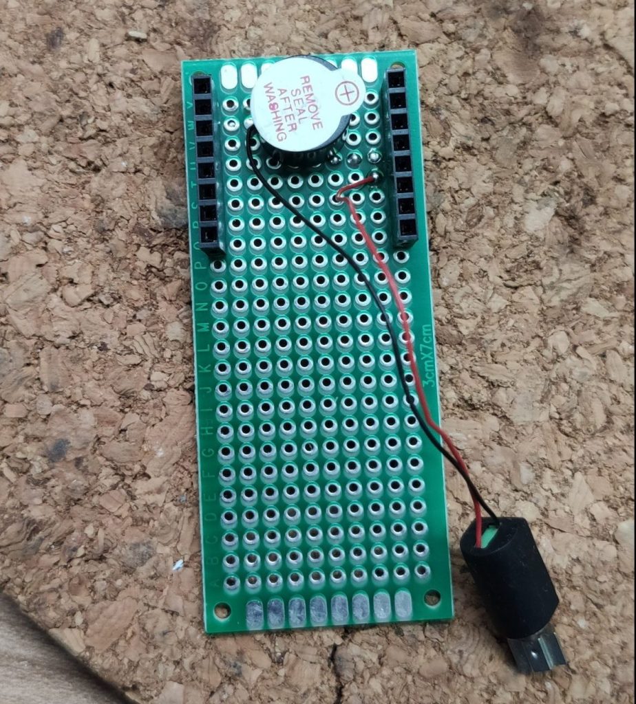
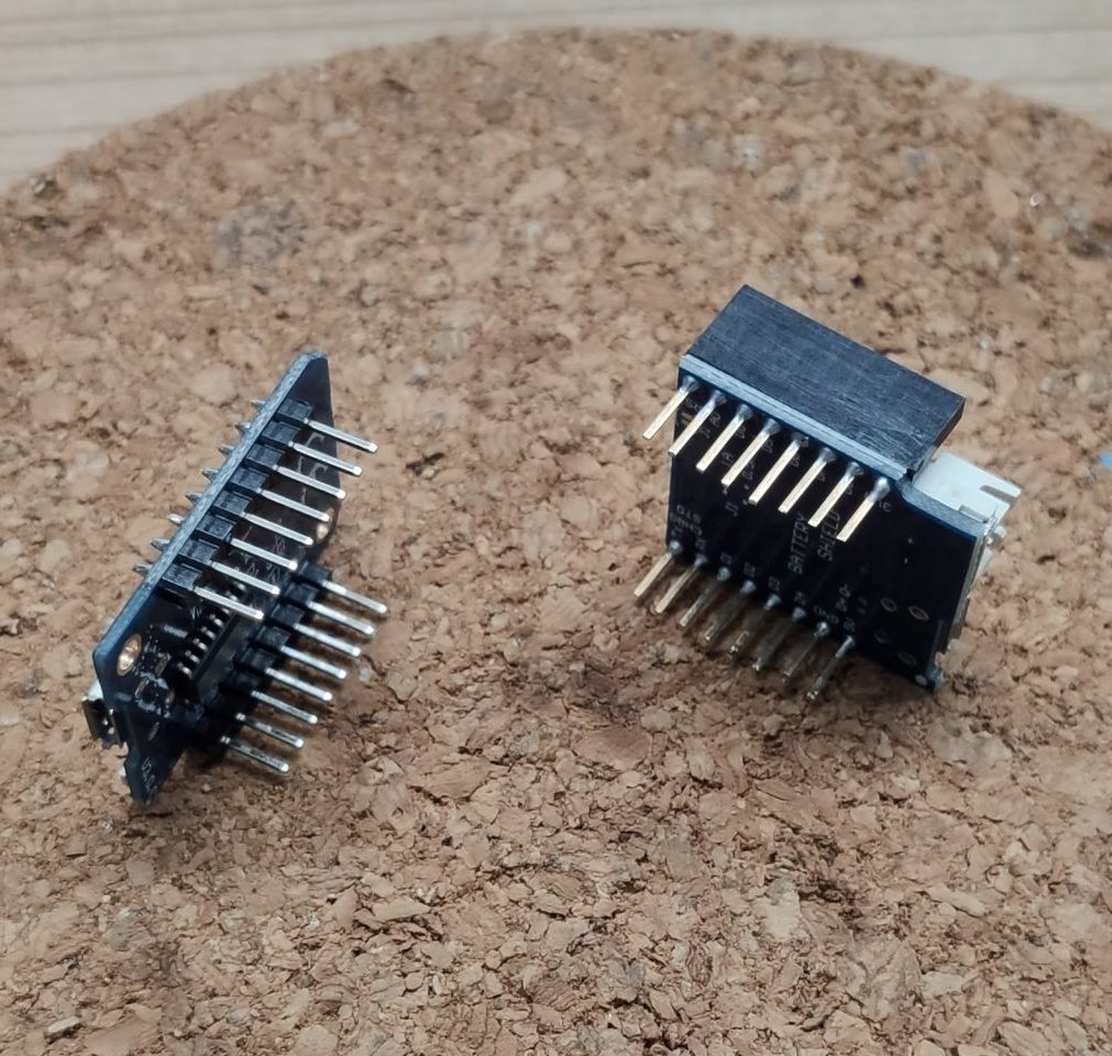
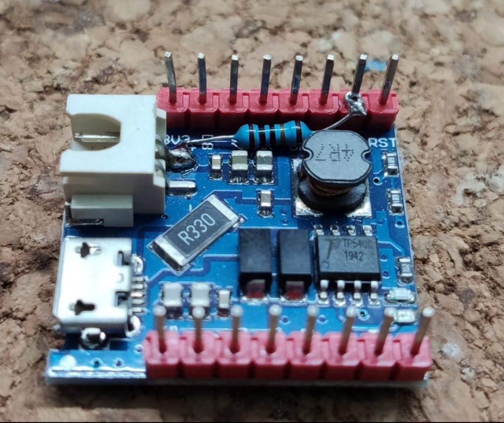
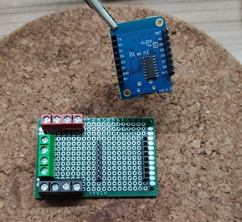
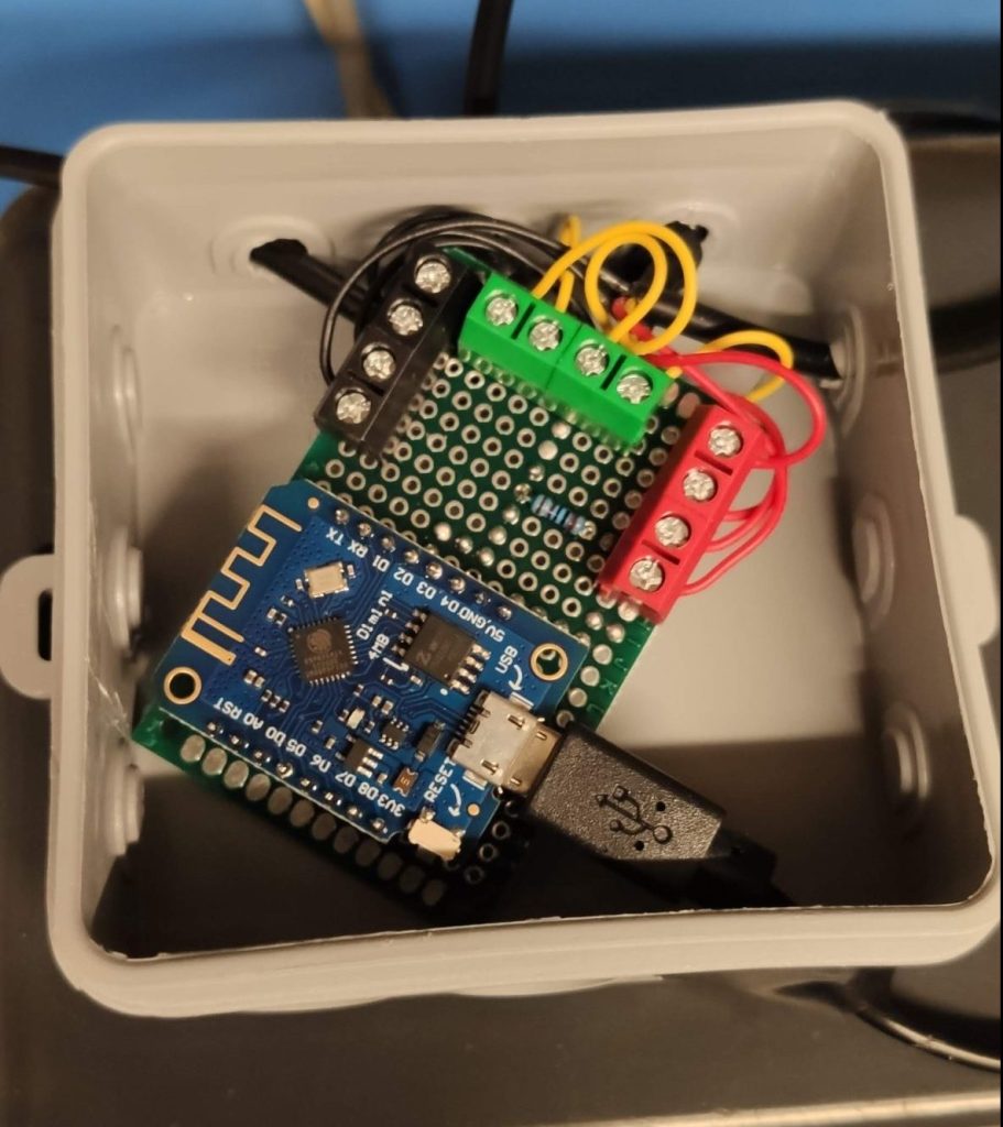
Let’s start by placing the screw terminals onto perfboard. I chose to use red for VCC, black for GND and green for data. That way I don’t get confused during connecting the sensors to the board later on. After placing the terminals, solder them to the board. Thx to the sensors, all data ports can be soldered to one dataline (Pin) on the D1 Mini so all data terminals can be bridged.

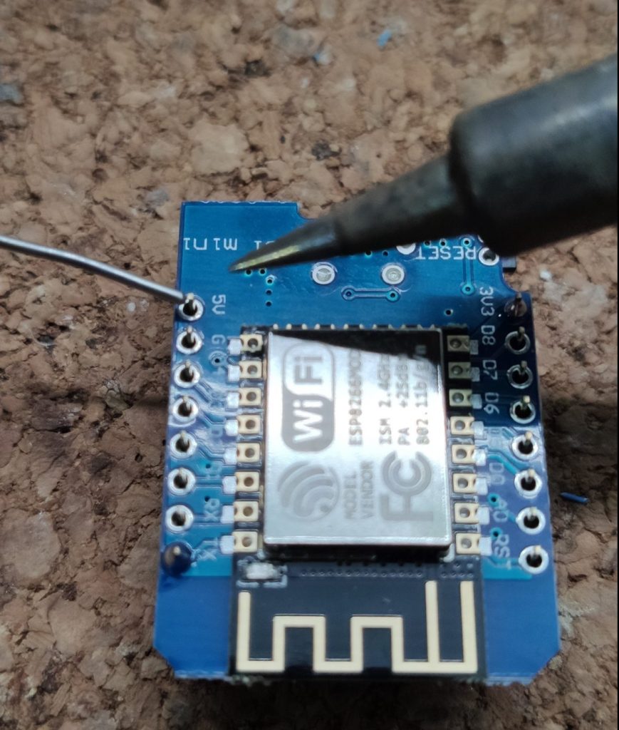
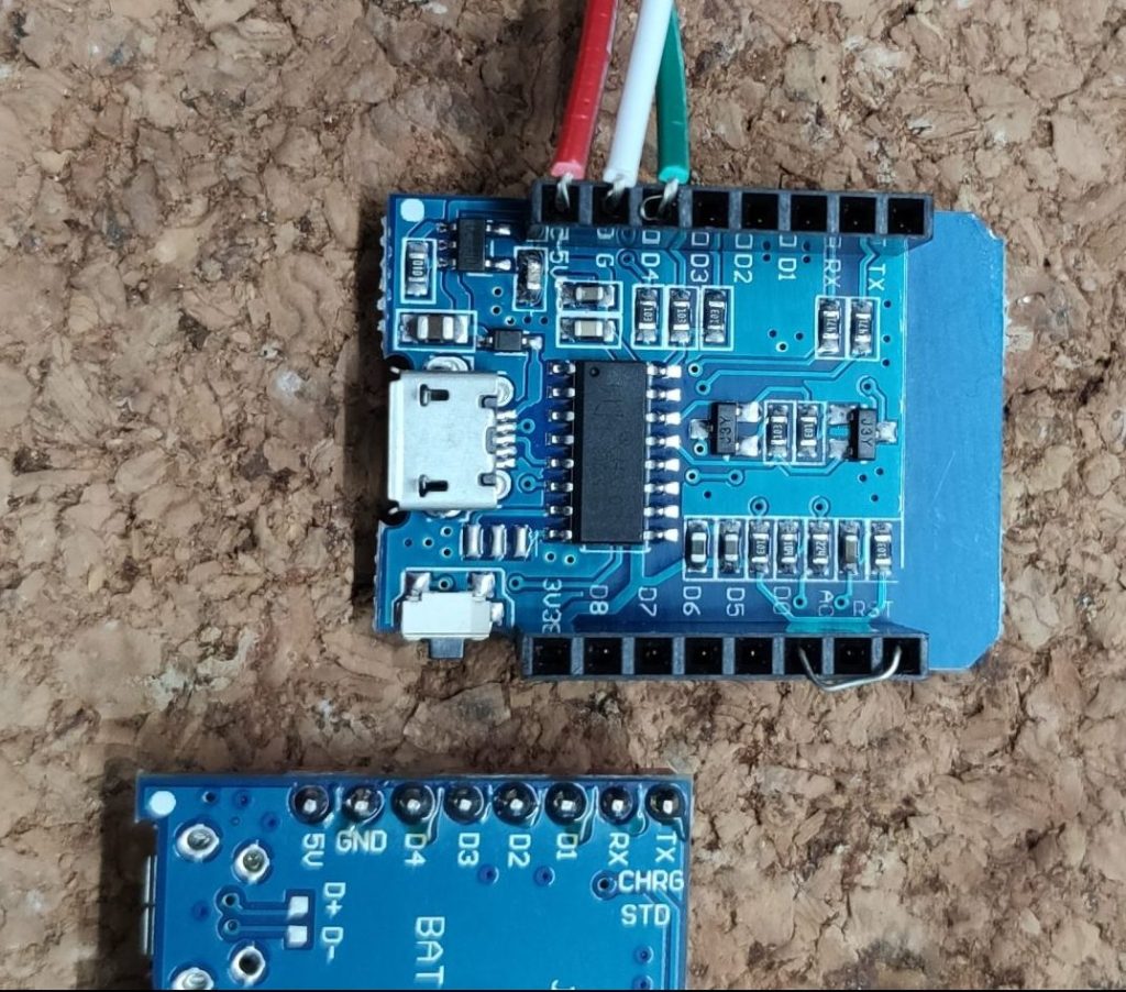
After that, figure out where the D1 Mini has to go. I placed it with the USB port up. That way the pins for VCC, GND and some data pins are facing the screw terminals. Further I soldered one male and female pin header to the board. With this setup it’s impossible to put the D1 Mini in the wrong orientation later on.
Choose a pin
Because all sensors will use the same data pin, connecting the sensors to the D1 Mini is quite easy. In my case I selected pin D2 (GPIO4) as the data pin. To prevent the pin from floating, its recommended to use a pull up resistor between data and VCC. ESPHome recommends a 4.7kΩ resistor but the board will use 4 sensors in parallel, so I decided to go with a 1KΩ resistor to create a strong pull up. Choose the value that fits for your setup.
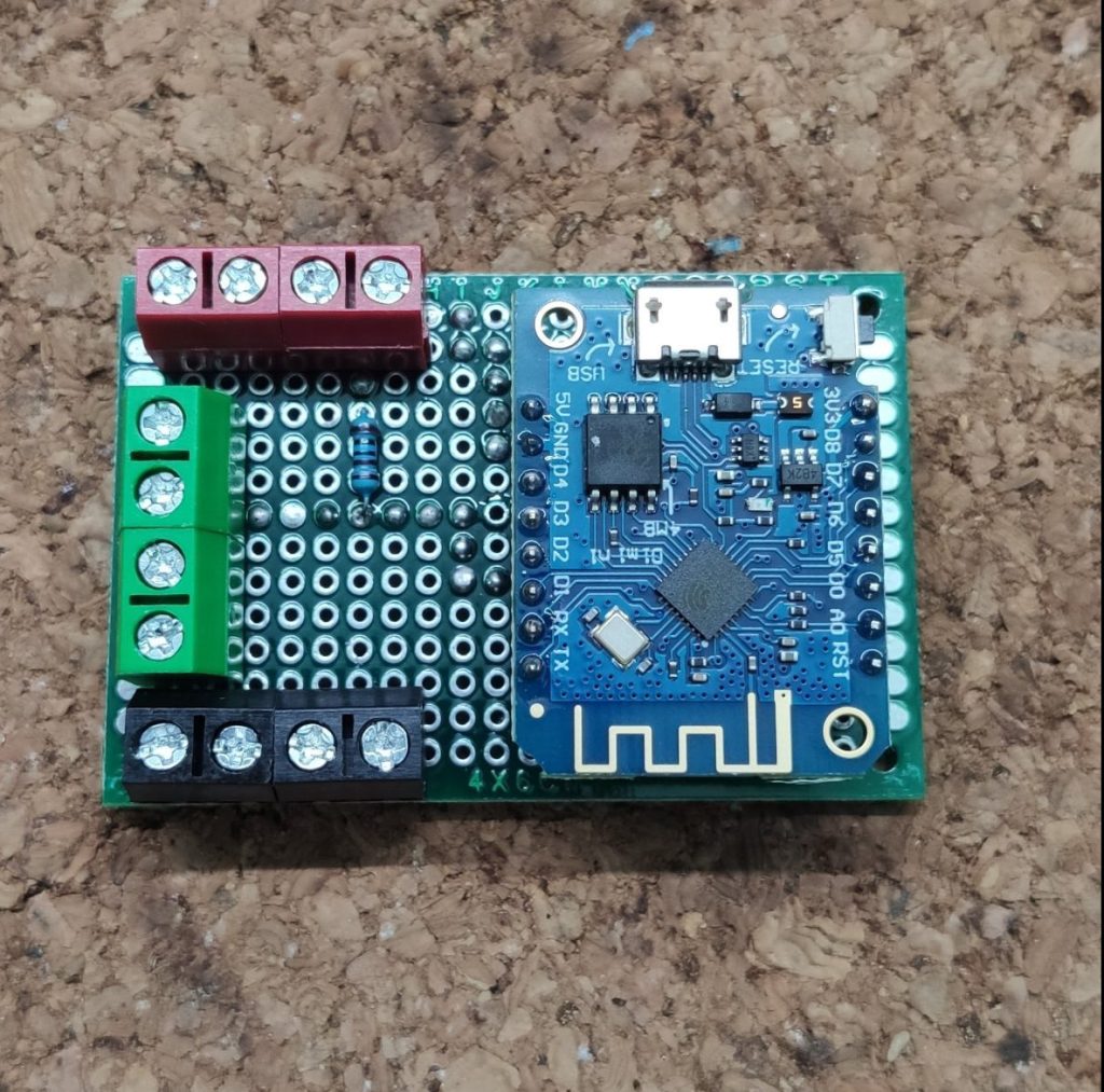
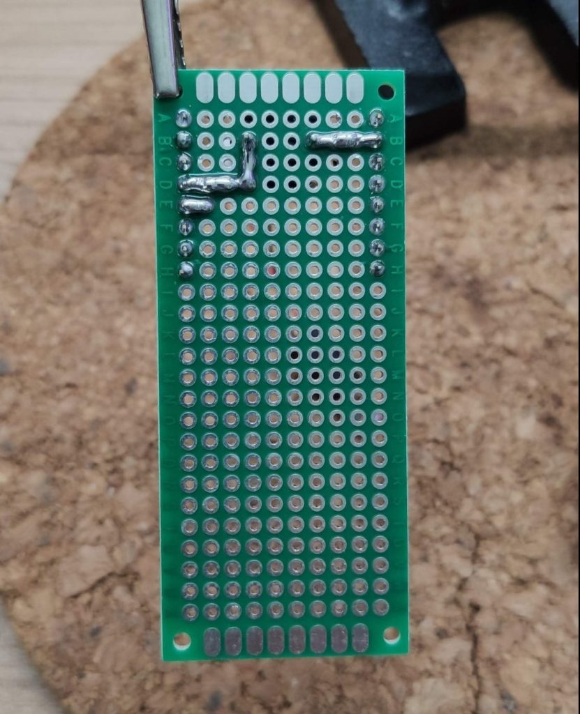
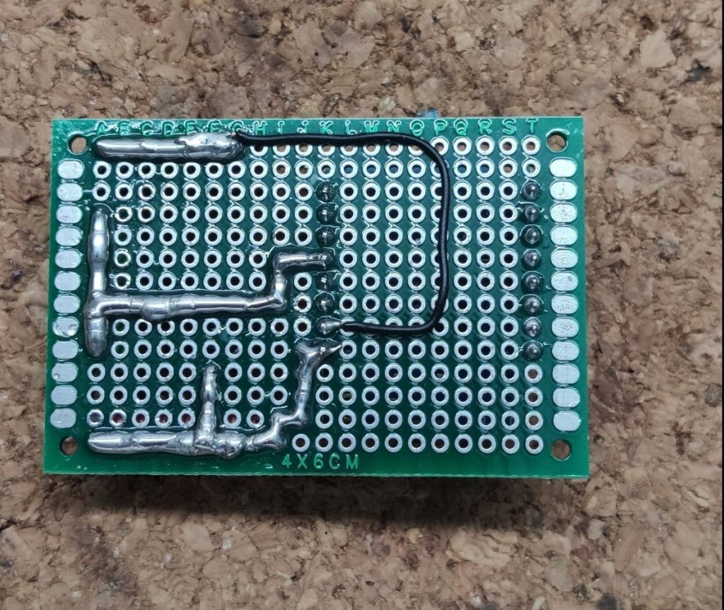
Finalizing the board
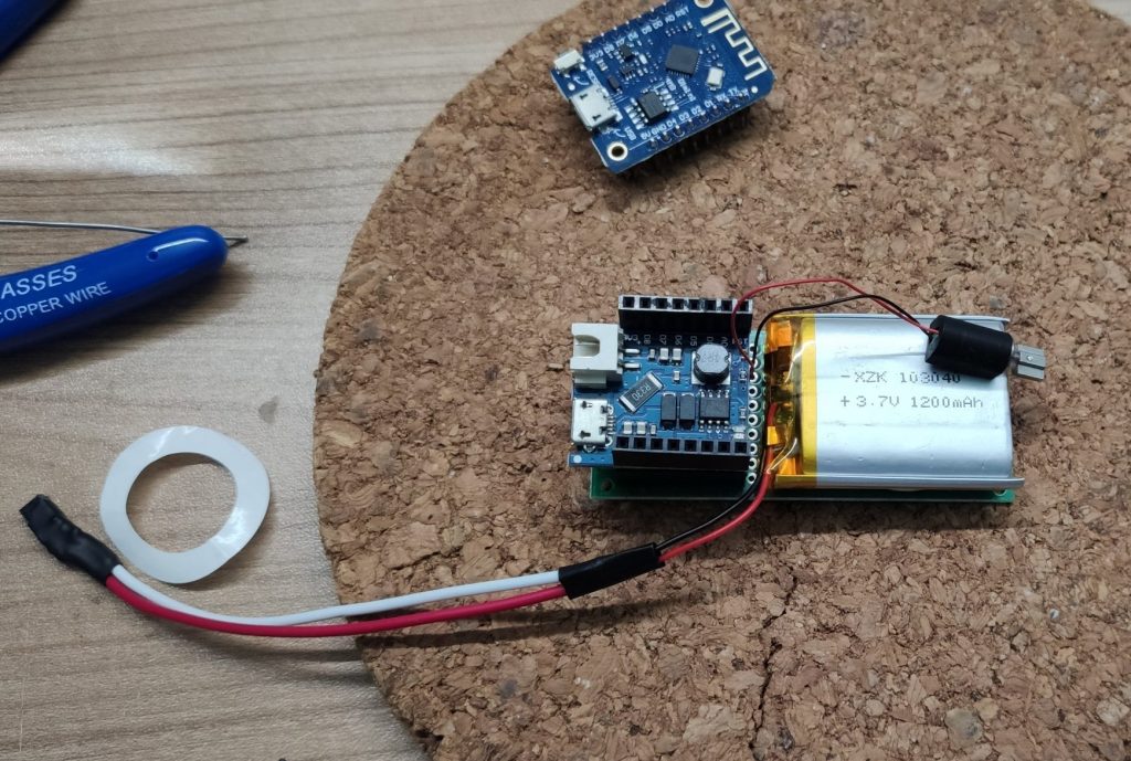
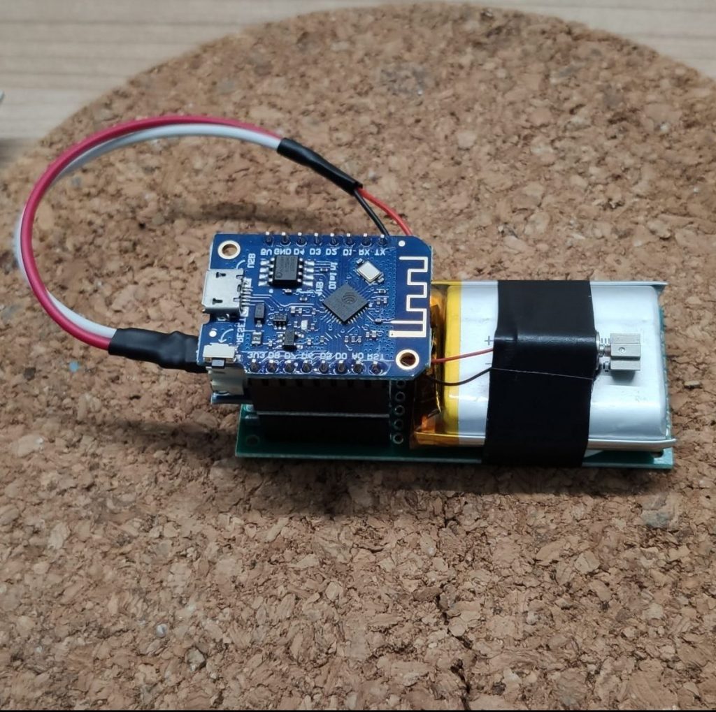
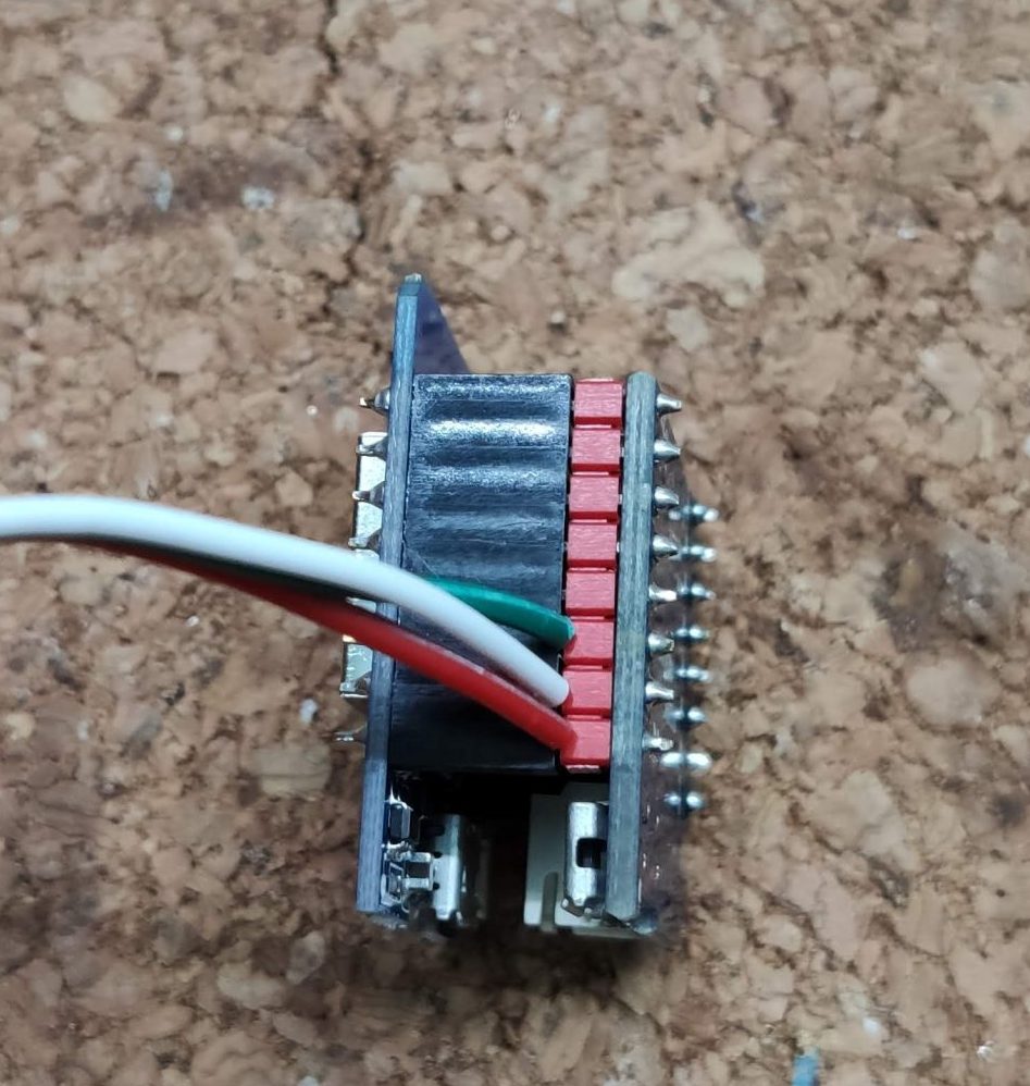
To provide the sensors with power, they must be connected to the D1 Mini. This is done as same as the data line, from the backside of the board. Its possible to simply bridge the pads or if you have a small spare wire, like me, just use that to connect the screw terminals. I used both methods to connect the GND and VCC terminals to the D1 Mini. The D1 Mini it self uses the power from the micro USB port.
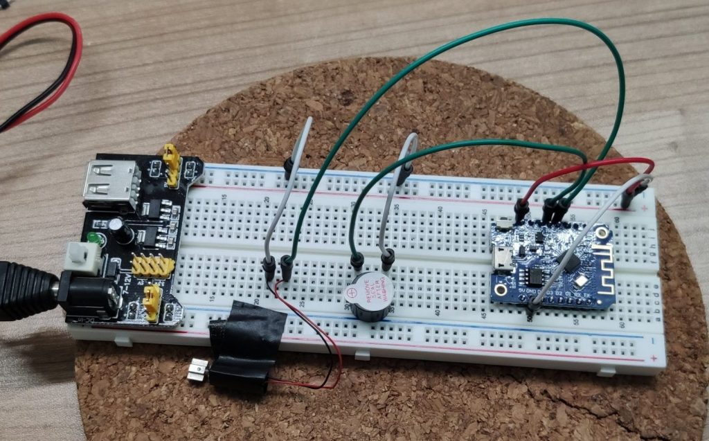
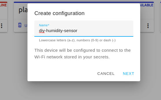
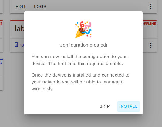
Into ESPHome
After all the soldering, its time to connect the D1 Mini and write / flash the ESPHome sketch. You can do that using the ESPHome web flasher. The easiest way to configure the sensors is to follow the recommendation in the ESPHome documentation. First prepare the basic sketch and connect one sensor. Then check the logs for the sensor address to specify it in the sketch and reflash the sketch after configuring the sensor. Repeat this process with all sensors.
Basic ESPHome sketch
esphome:
name: heaterroom-thermostat
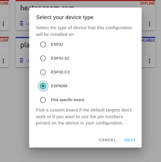
esp8266:
board: d1_mini
# Enable logging
logger:
# Enable Home Assistant API
api:
encryption:
key: "auto-generated-key"
ota:
password: "auto-generated-password"
wifi:
ssid: !secret wifi_ssid
password: !secret wifi_password
# Enable fallback hotspot (captive portal) in case wifi connection fails
ap:
ssid: "Heaterroom-Thermostat"
password: "$up3rP4sSw0rd"
captive_portal:
#temperature sensors
dallas:
- pin: D2
The final sketch should look similar to this one.
Final ESPHome sketch
esphome:
name: heaterroom-thermostat
esp8266:
board: d1_mini
# Enable logging
logger:
# Enable Home Assistant API
api:
encryption:
key: "auto-generated-key"
ota:
password: "auto-generated-password"
wifi:
ssid: !secret wifi_ssid
password: !secret wifi_password
# Enable fallback hotspot (captive portal) in case wifi connection fails
ap:
ssid: "Heaterroom-Thermostat"
password: "$up3rP4sSw0rd"
captive_portal:
#temperature sensors
dallas:
- pin: D2
# Individual sensors
sensor:
- platform: dallas
address: 0x61b0d35b1f64ff28
name: "Probe 1"
- platform: dallas
address: 0x753d852d1864ff28
name: "Probe 2"
- platform: dallas
address: 0x0f9e4b221864ff28
name: "Probe 3"
- platform: dallas
address: 0x6623872d1864ff28
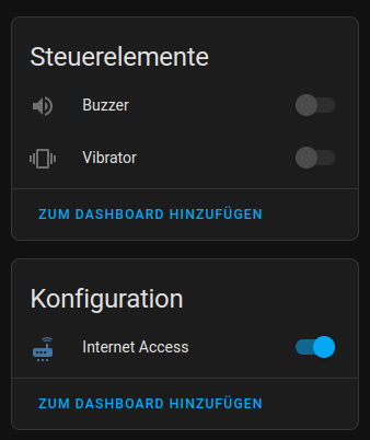
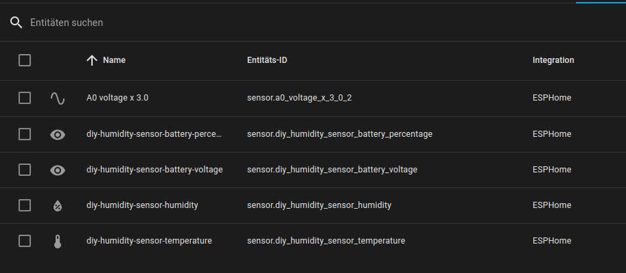
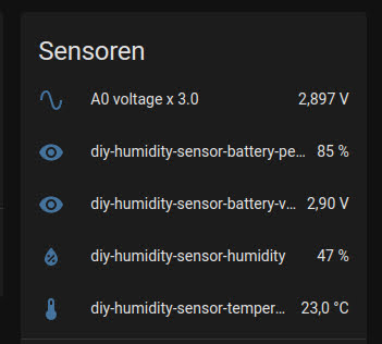
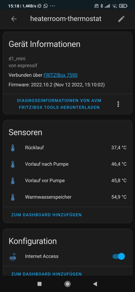
name: "Probe 4"If all sensors are configured properly the ESPHome device can be added to Home Assistant. It shows up as a regular device and promotes all the configured sensors which then can be renamed and added to a Home Assistant dashboard.
Mount all the things
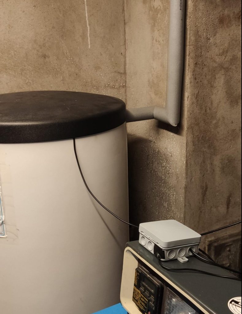
With all the configuration done, its time to mount the sensors to the heating system. I mounted the sensors at 4 points. The first one is the hot water tank. The sensor connects to the exposed metal on the top of the tank which is covered by isolation material.
The second and third sensor connect to the fore-run of the heating system. One before and one after the pump. That way I can see if something is wrong with the pump, if these temperatures differ much.

The last sensor connects to the return-run of the heating system. That measurement must always be lower than the fore-run, otherwise something is badly wrong 😂. All sensors are fixed with zip tiles and covered by some isolation material to get the most accurate readings.
Last not least, I placed the board into a electrical junction box to protect it from dust and powered it with a phone charger. Pick an enclosure that fits for nearly every enclosure should work.
Sum Up
And that’s it! Your central heating system can now be observed in Home Assistant. The readings might differ a 0.5 – 1.0 degree from the in-pipe-thermostats, but this should not be a big deal if you’re monitoring such an old system😉.
If you like this project feel free to share it and if you have further questions, hit me up on twitter or in the comments below😎.