Generally speaking, vasemode prints are awesome! They are fast, did not often fail and also have no stringing at all cause there is no retraction used. But there is also a downside. Vasemode prints are not that rigid as regular prints because they only use one perimeter during the whole print. So how can we increase the strength of a vasemode print? These are the 3 techniques I use to make my vasemode prints more rigid.
Technique 1: Overextrude / upgrade to a bigger nozzle
Sounds stupid, but one simple way to add more strength to your prints is to extrude more material. This can be done by switching to a bigger nozzle like a 0.6mm one. The bigger nozzle diameter will extrude more material which makes the one perimeter stronger. But what if you don’t want to upgrade to a new nozzle cause you only print sometimes in vasemode and want to keep you standartd 0.4mm nozzle that may came with your printer?
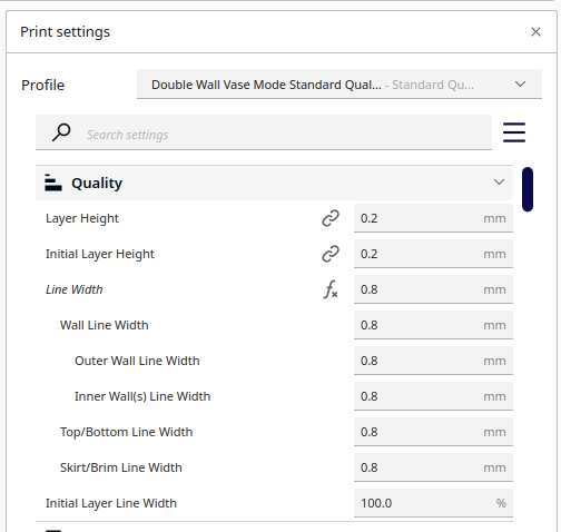
Well than you have the possibility to overextrude material. If we advice the slicer to push more material through the hotend then regular, that will also end up in thicker and more rigid perimeter. But this comes with a downside, overextruion is limited because it will clog your nozzle if you get to greedy with the material. E.g. if you try to push material for a 4mm perimeter to a 0.4mm nozzle, which would be 10x more than regular.
In my tests I found out that you can safely extrude twice the material through a standard 0.4mm nozzle. So setting the default perimeter/wall width to 0.8mm will increase the strength of your print in a decent way.
Further, keep in mind to slow down your print speed and increase the temperature a bit while overextruding. This gives the material more time to melt in the hotend and prevents clogging.
Technique 2: Use fuzzy skin
I found this “trick” recently by accident cause I forgot to uncheck that option as I printed some decorative vases. As I saw the final print I was quite impressed how stiff the model actually became and after thinking about the “why” it also made kinda sense to me.
Here are my 5 Cents on that. On a fuzzy print the nozzle wiggles during the extrusion process. Because this wiggle is kinda random it creates tiny pits in the perimeter which, if you see it kind as a half sphere, gives the perimeter more structural integrity.
Of cause this has also a downside. If you get too fuzzy, your perimeter start to get holes and if you need a very smooth surface you can totally skip this technique. But to add some more strength to a simple vase, this is a very good opportunity.
Technique 3: Design your model for vasemode
This technique is the holy grail of strong vasemode prints and mostly dedicated to designers. You can actually design your models in a way that they are more rigid in vasemode. This is done by a couple tricks which increase the strength of your model and keep it vasemode compatible.
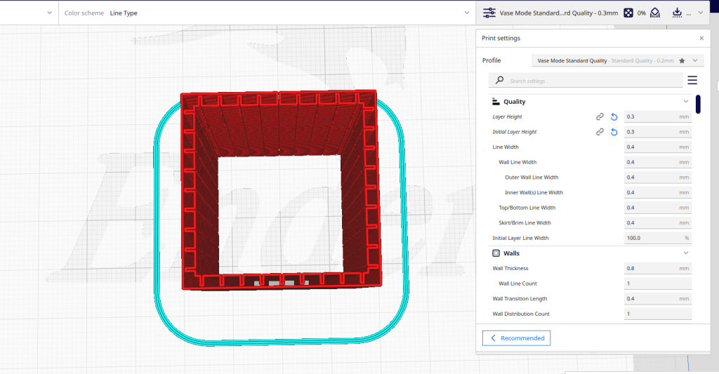
Lets imagine you want to have a square tube with an insider and outside perimeter.
Step 1.
First you have to create a cut through your whole model, from bottom to top. This makes the print compatible with vasemode because the cut connects the inside and the outside perimeter. Now it comes to the trick.You make the cut so thin, that during the printing process, the two sides of the model will melt together and creating a seam.
The Seam is at the top center
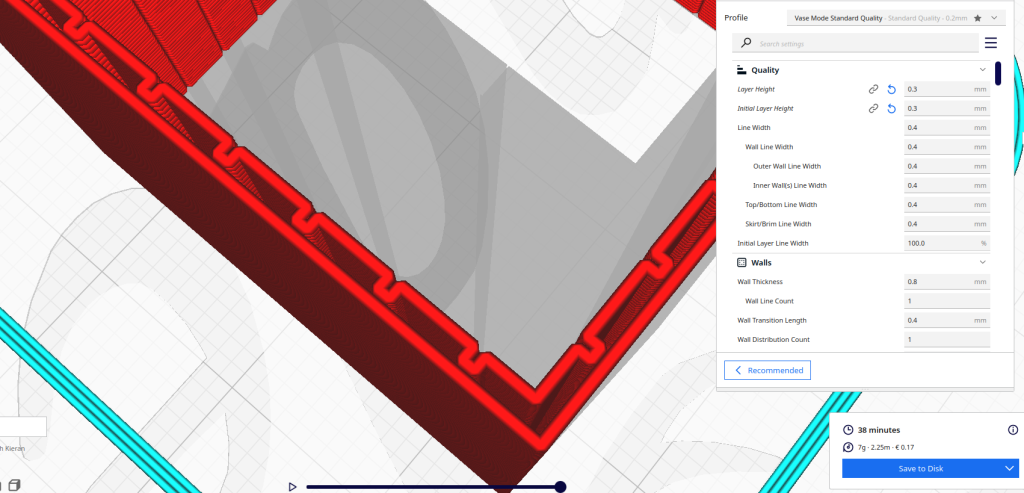
Step 2.
To increase the strength you can now add ribs between the inside and outside perimeter. This is also done by cuts witch don’t go completely through the model and form a u-turn during the slicing process. The distance between the outside perimeter and the cut is two times the nozzle diameter if you are using Cura. The width of the cut was in my testing one times the nozzle diameter. Everything smaller was wiped by Cura during the slicing process🙄.
If everything works as expected you should see, that the end of the u-turn touches the outside perimeter. These ones will also melt together during printing.
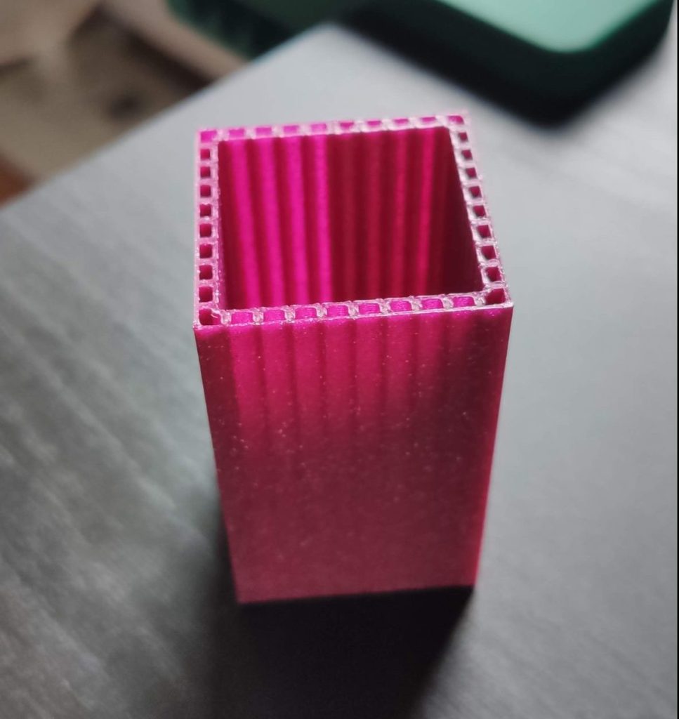
After the print finishes, you can see that both perimeters are connected by the ribs which makes the vasemode print extremely strong depending on the amount of ribs you used.
But as same as the both other techniques, this one has also his downsides. First you can’t do this with downloaded STL files cause the designer has to follow the named tricks during the design process. So it’s more dedicated to the people who creates their own models using CAD software.
Second, because this technique relies on margins and dimensions of the perimeter distances, you can’t simply scale these kind of models. E.g the model above could be scaled in Z but not in X or Y cause this would increase the distance from the ribs, seams, etc. If you have an even more complex shape you also can forget the Z scale.
Last not least, this technique is time consuming. You have to tinker a lot to find settings that work for you and you also have to keep the vasemode tricks in mind during the whole design process. But all in all this will give you the best results for strong vasemode prints.
Conclusion
As shown above there are several possibilities to the increase the strength of your vasemode prints. From super simple to more complex. You should check them out to see which one works best for you 🤓. If I had to choose one to start with. I would try the fuzzy skin technique, because its super simple to use and require not a lot of changes in the slicer.