Combining old and new things is something I really like. I often see things and think: “Woaw, how would that look with LED’s on it?” I also like to be inspired by others and try to rebuild projects they built. That happened to me lately as I saw the frame lamp, Paulus from the Home Assistant team built. The idea was so cool that I wanted to build my own version of this frame lamp, so I started to look for the components I needed for this project.
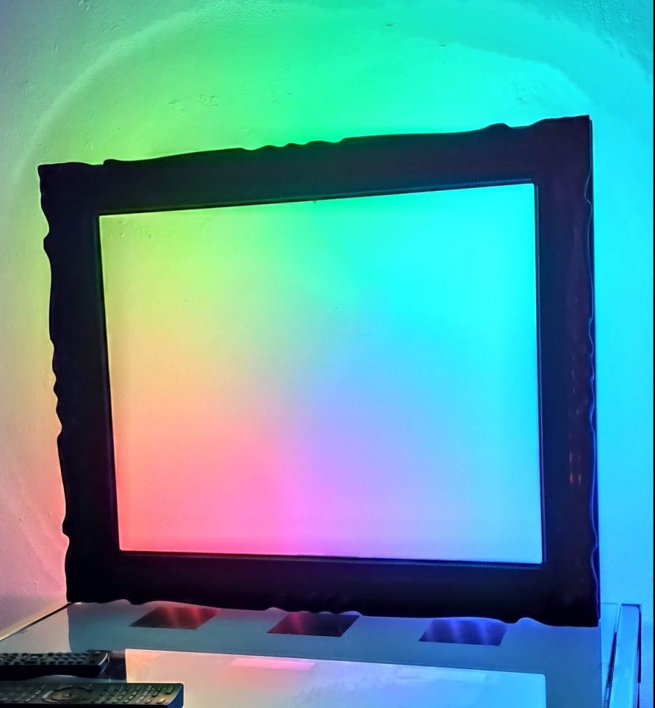
The finished lamp with rainbow effect
Parts list
For this project we will use the following components:
*Some links are affiliate links. If you use them to buy the parts for your project you will help me and my next project. These links will cause no extra fee or costs to you
All components
Start building this thing
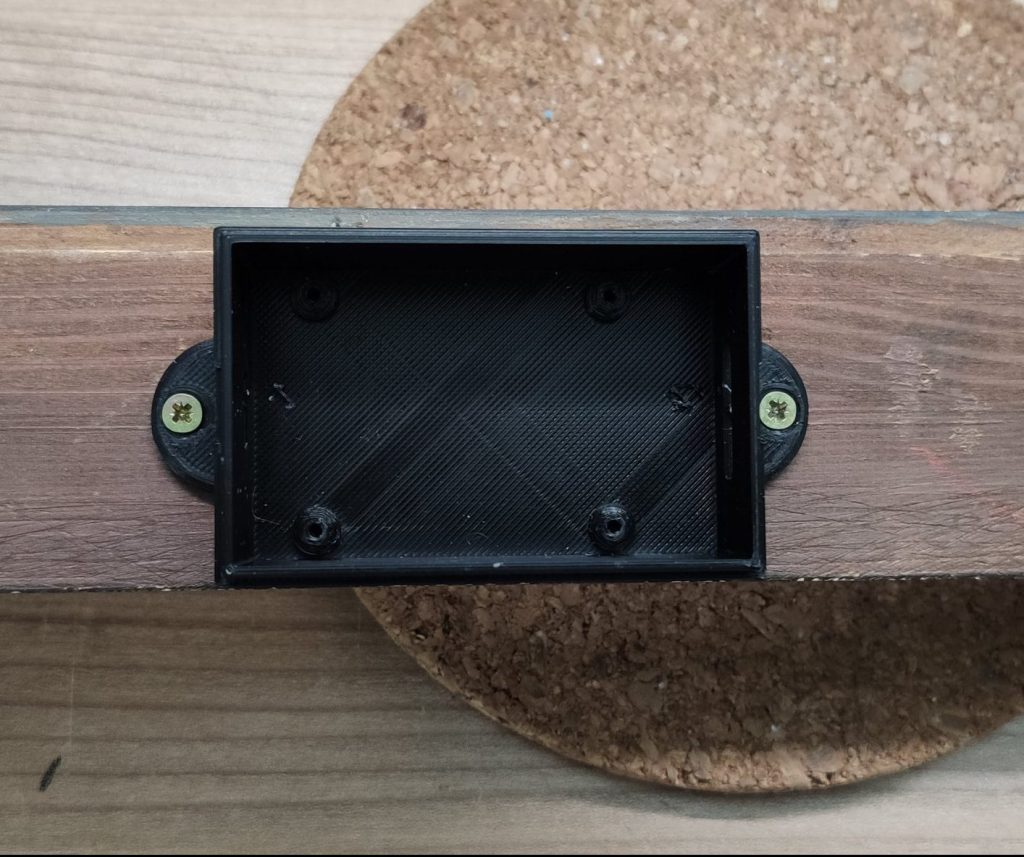
Start with centering the Dig Uno case in middle of the backside of the frame and screw it down. The case and the two angles will work as stands for the frame later on. Alternatively you can skip this step if you want to hang the frame.
Dig Uno case screwed on the backside of the frame
Next up, solder three cables to the beginning of the led strip. If your strip is brand new you can simply snip off the connector because the wires will be connected directly to the Dig Uno.
Soldered cables on the LED strip
Cut the strip
In this step, the strip will be cut and lined up with the frame. Check the dimensions of the frame and cut the strip in parts so that it fits on the backside including the corner connectors. This step is just to find the right dimensions for the strip, don’t glue it down yet.
Aligned strip on the backside of the frame
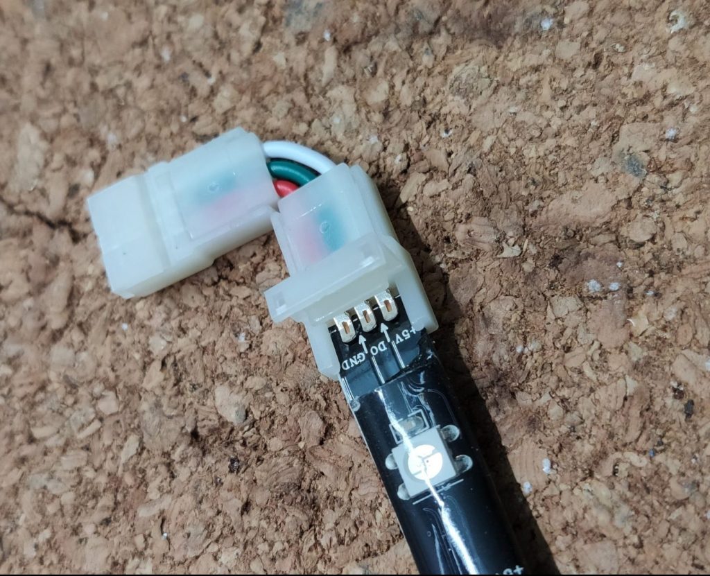
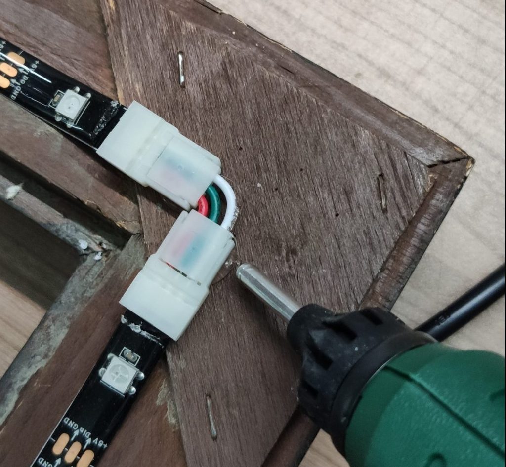
If the strip has a good length for the frame, connect the strip using the corner connectors. If you’re using IP65 strips like I do, you have to cut off a bit of the silicone coating.
Strip connected to the corner connector
Testing and hot glue
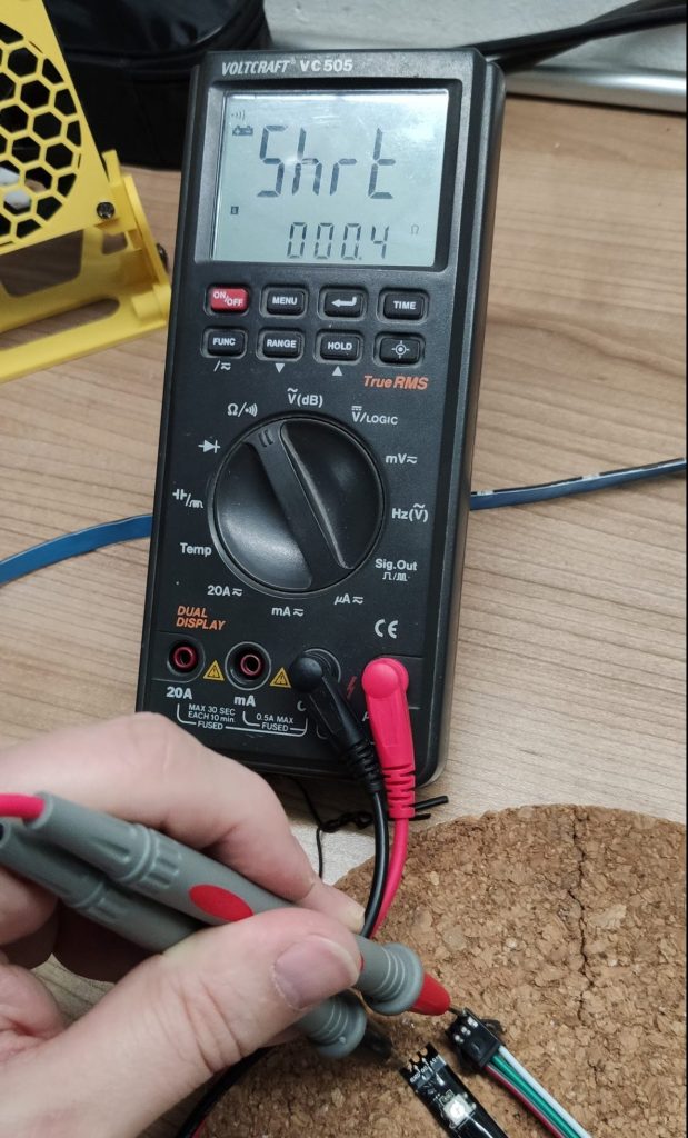
Before you glue down the strip to the frame, give it a test using a multimeter in continuity test mode. You should test the positive and negative rail to ensure that both have a good connection. Keep in mind that this will not work on the data-rail of the strip. If one of the two rails don’t work, check the connections on the corner connectors.
Testing the connections
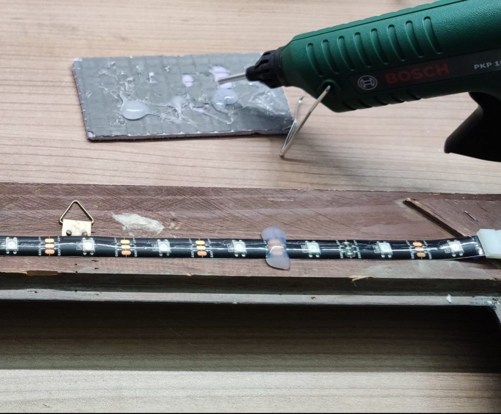
Next up, pull off the blue PVC from the double sided tape on LED strip and glue it to the frame. Then heat up you hot glue gun and hot glue the heck of it 😅 ensure that all corner connectors are glued down to the frame so that nothing can fall apart or loose connection.
Corner connector glued down
If you have so much trust into the double sided LED strip tape than I have, you can add some extra hot glue to the strip.
Double secured LED strip 😬
Connecting the Dig Uno
In the final section we will connect the Dig Uno to the strip and place it into the case. If you don’t know what a Dig Uno is, no problem! You can find all information about it on the quinled.info website. You can either buy a pre-assembled board with WLED installed or, if you’re a DIY lover like me, you can build the DIY version and get your hands dirty, which is a lot of fun 🤩
So grab the Dig Uno and place it into to case mounted on the frame. Then connect the LED strip to the controller board.
Connected LED Strip
Last not least connect the power supply to the Dig Uno as well.
Connected power supply to the Dig Uno
Build the stand
This step is optional, if you want to hang your frame lamp. But if you want to stand up the frame the angles on corners of the frame will give the whole construction more stability. So take the angles and screw them to the corners of the frame.
Angle stand for the frame
Final test
That it! So turn the frame and power it up to the the awesome result 😎 The frame works best on a white background, cause this will reflect the LED light better than a dark background.
The final result
Sum up
I really like this project, because its easy to build, requires nearly no soldering and it just looks beautiful. Big thx again to Paulus form Home Assistant for this idea and stunning result. 🤗
Smart devices, especially lights, are super cool. But with the smartness of a device mostly comes a trade off in manner of power consumption and complexity. This is not always needed and makes the problem to solve often bigger than it actually is. I ran in this situation recently and caught myself standing in the front yard thinking hard about how to increase my WiFi range for installing a smart light🤦. Because I couldn’t solve the WiFi problem, I started from scratch and ended up with a much more simple solution which works out perfectly. A DIY battery powered PIR outdoor light 🤓.
Battery powered PIR outdoor light
Parts list
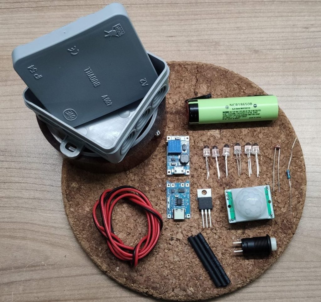
For this project we will use the following components
An electric junction box (from your local hardware store)
*Some links are affiliate links. If you use them to buy the parts for your project you will help me and my next project. These links will cause no extra fee or costs to you
All components
How does it work?
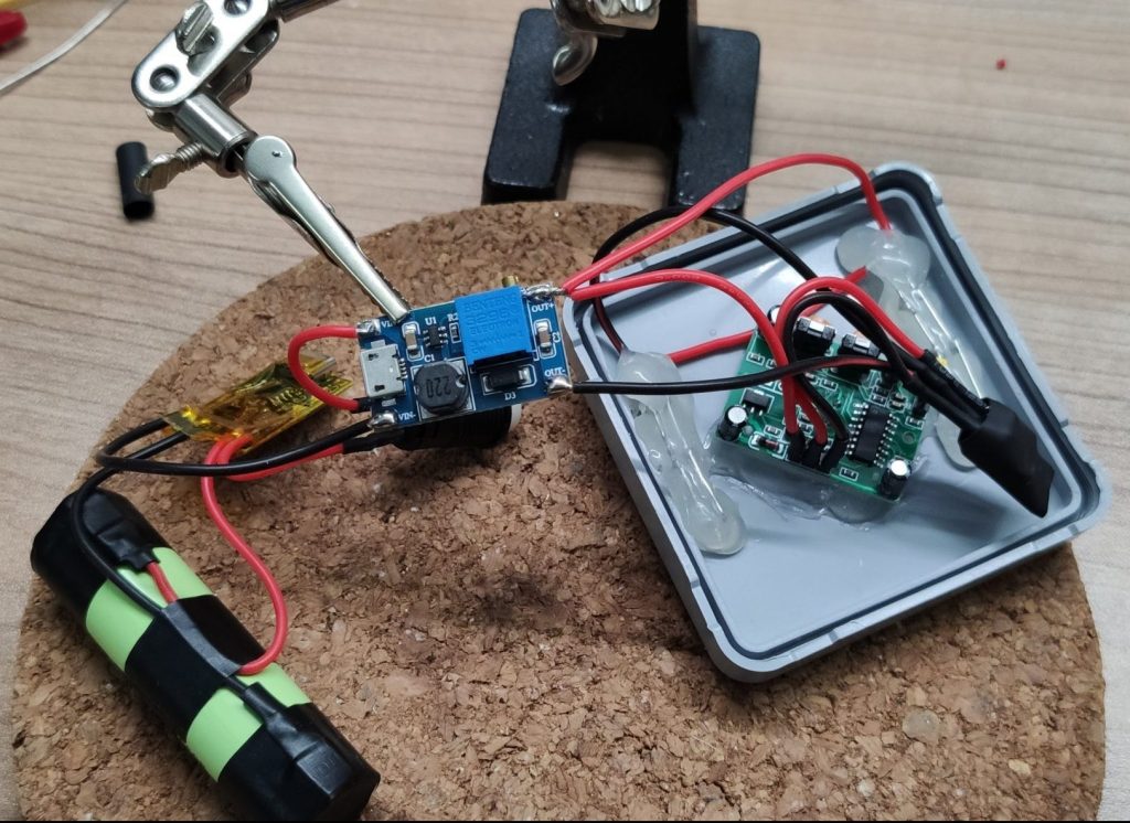
The PIR sensor, the LED’s and the MOSFET are connected to the DC-DC step up converter which is powered by the battery. If the sensor recognizes motion from dusk on, it will trigger the gate of the MOSFET, which than acts as a switch and turns the LED’s on for a certain amount of time. If the battery runs out of power, it can be simply recharged via USB. Last not least, the whole circuit can be turned off using the button. And all this without a single line of code 😍.
Start with the power
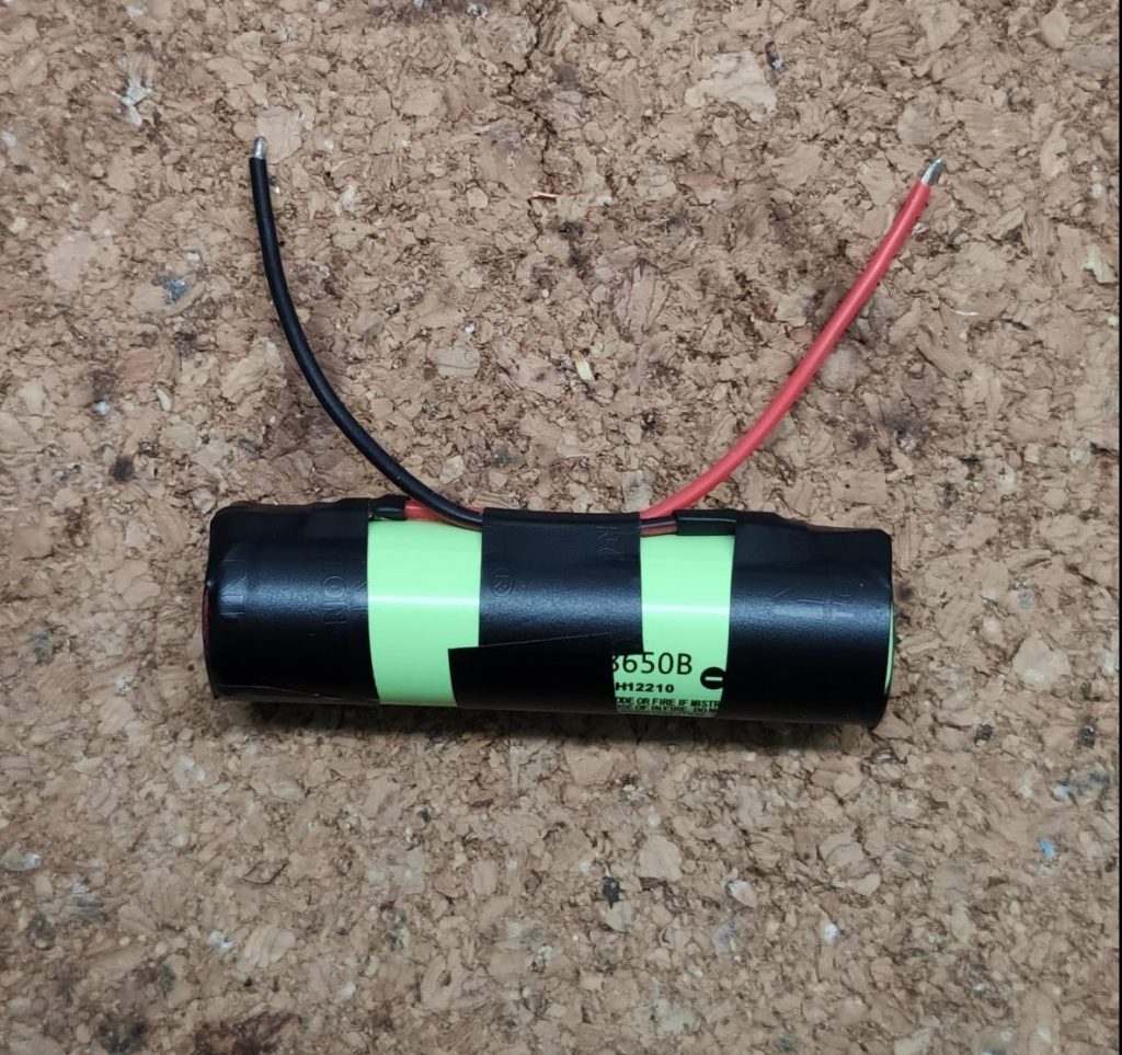
We will start with building the power circuit first. So grab the rechargeable battery and solder the some wire to the plus and minus pole. To prevent shorts later on, ensure that you will wrap the open sides of the contacts in isolating or Kapton tape.
prepared battery
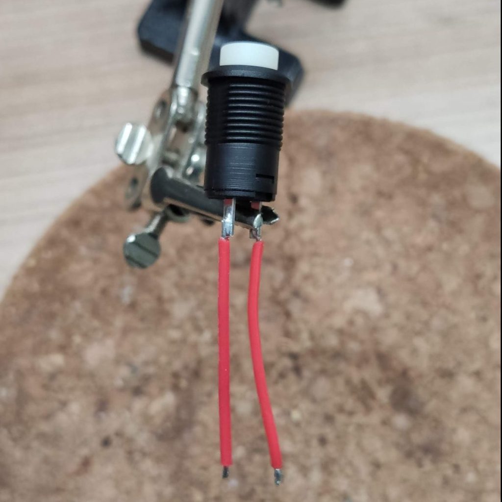
Grab now the push button and solder two wires to it. In my case I used red wires, because I want to disconnect the positive side of the circuit with the button. As same as on the battery protect the solder joins with heat shirks or isolating tape.
prepared button
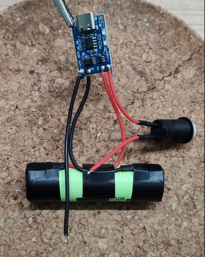
Combine the charging unit with the battery and the button in the next step. Solder the battery to the battery pads and the switch to the positive load pad. Grab and extra piece of wire and, black in my case, and solder it to the negative load pad. So you end up with two wires which can be connected to a load.
Connected batter charging unit
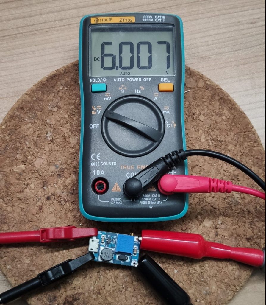
Because the HC-SR501 needs at least 5V to operate, we have to adjust the DC-DC step up converter in the next step. I selected 6V at this point, because I needed 6V for the arrangement of the LED’s I used. If you want to use e.g. a 5V led strip instead, simply adjust the voltage to your needs.
The adjusted converter
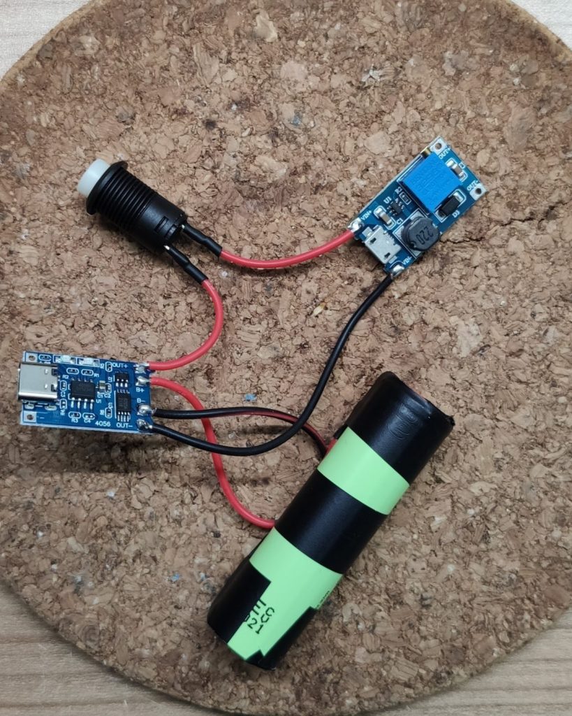
If the converter is adjusted solder the input side to the two wires of the previous circuit. This completes our power supply.
If the button is pressed it connects the battery through the charging unit with the step up converter which provides 6V. If we want to charge the battery we disconnect the step up with the switch and can safely plugin a USB cable to the charging unit.
The finished power providing circuit
Move on to the enclosure
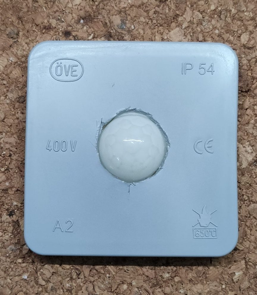
In the next step we will focus on the enclosure of the outdoor light. Grab the lid of the electric box and cut a hole into it so that the cover of the HC-SR501 fits in. Have a close look at the orientation. I had to place it diamond ways so that it will fit with the LED’s.
Electric box cutout
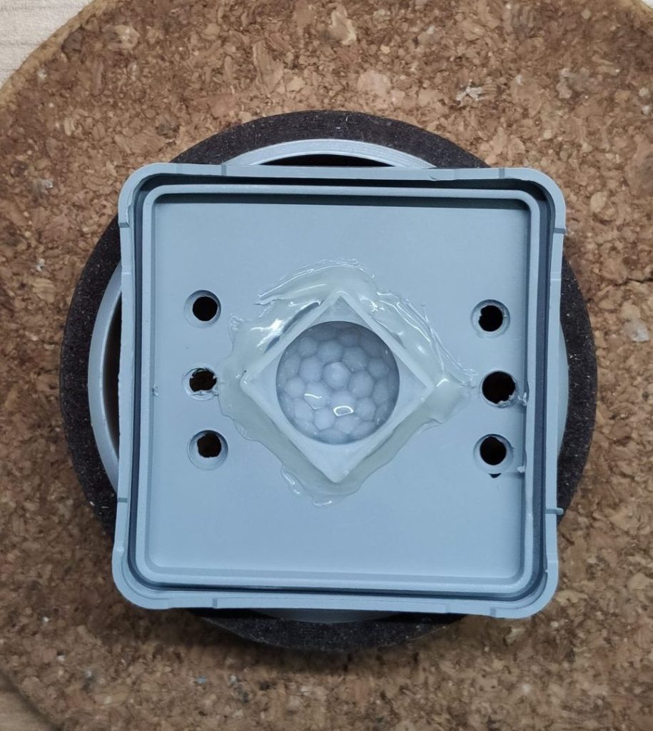
Secure the sensor cover with hot glue form both sides to make it kinda weather proof. Next, grab a drill and drill 6 holes for the LED’s inside the lid.
Lid prepared for the LED’s
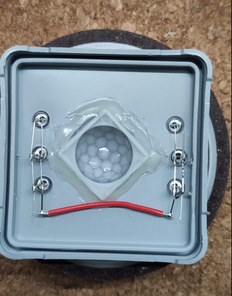
In the next step, place the LED’s inside the lid and connect them with a piece of wire. I decided to use two pairs of three LED’s in parallel, connected in series. That way three LED’s in parallel will need 3V and the two LED packages in series (six LED’s) can be powered with 6V without any problem. Thats also the reason why I chose white LED’s because each of them has a operating voltage of 3.2V max. If you solder the LED’s keep an eye on the polarity, if you mixed them up, they will not work.
Prepared LED’s
BTW: I know many people will now yell: “You have to use dropping resistors for the LED’s🤯 “. Yes I should… but YOLO!! We’re working with six cheap LED’s in this outdoor light and it works perfectly that way, trust me 😉.
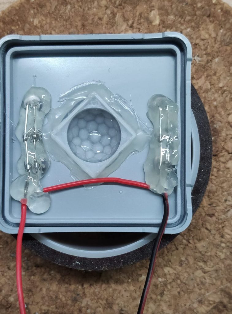
To finish the lid, solder two wires to the positive and negative side of the LED’s and flood them in hot glue for a better weather resistance.
Finished lid
Prepare the MOSFET and the PIR sensor
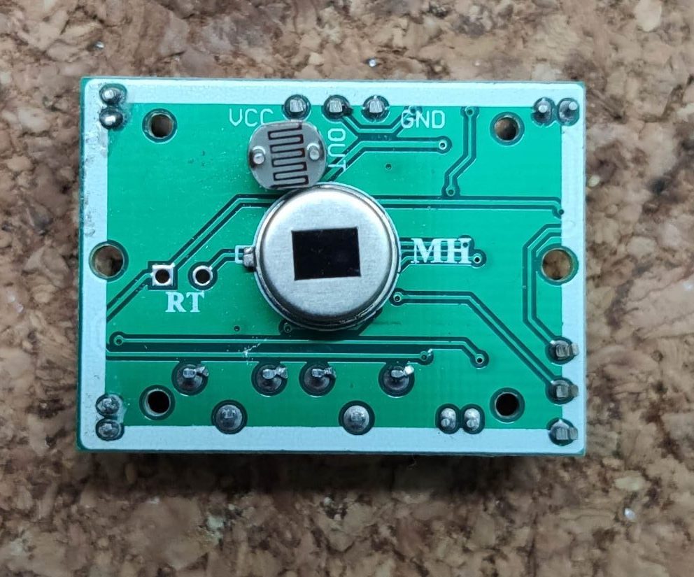
Lay the lid with the LED’s aside and prepare the PIR sensor. Take a close look at the board. You will find two wholes above the infrared sensor, with the marking “LR”. Take the LDR and solder it in that place. Be aware of touching the infrared sensor with your fingers, this would affect the functionality of the sensor.
Prepared sensor
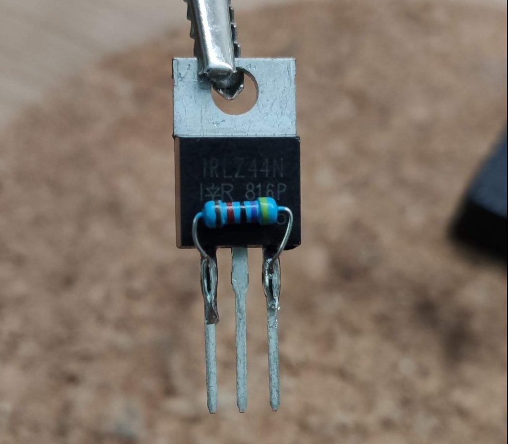
Lets now move to the funny part of the project and grab the IRLZ44N MOSFET to solder the 47KΩ resistor on it. Solder the resistor between the gate and the source of the MOSFET. This ensures that the gate is always pulled low if now signal is provided from the PIR sensor. If you’re unsure which pins to use, checkout page 8 in the MOSFET datasheet.
FYI💡: In general you can use any kind of NPN MOSFET as long as it is a logic level one.
Resistor + MOSFET
In the next step we will wire up the MOSFET. Grab two pieces of black wire and one red one. Remove some isolation from the two black wires, twist the ends and solder them to the source of the MOSFET. In my case it’s the third leg. Then take the red wire and solder it to the gate of the MOSFET, in my case that’s the first leg. Add some heat shrinks to prevent shorts.
Last not least, grab the lid of the electrical box and solder the black wire of the LED’s to drain of the MOSFET. In my case that’s the center leg. After connecting the wires, you should end up with something like the picture below.
The MOSFET wired up
Connect the MOSFET, the PIR sensor and the LED’s
We will now connect the MOSFET and the LED’s to the PIR sensor of the outdoor light. Grab the PIR sensor, the red wire and one of the black wires of the MOSFET. Solder the red wire which comes from the gate of the MOSFET to the OUT pin of the PIR sensor and the black wire to the GND pin. As always, don’t forget the heat shrinks 😉.
MOSFET soldered to the PIR sensor
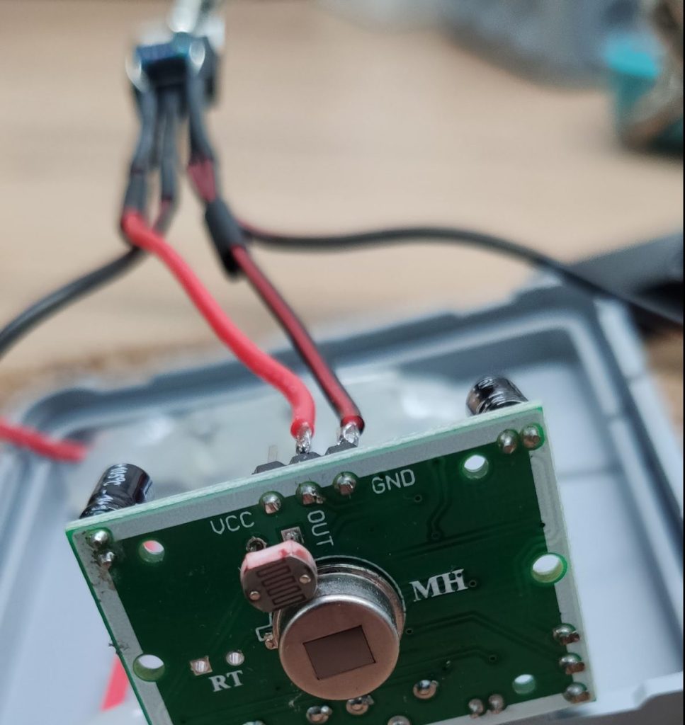
To connect the PIR sensor to our power circuit we’ll need one more piece of wire. This piece, in my case a red one goes to the VCC pin of the PIR sensor.
Sensor with soldered MOSFET and power wire
All in all you should end up now with the connected MOSFET, PIR sensor and the LED’s. From this combination you should have one black wire and two red wires left. If not, something went wrong so feel free to start over at the beginning of this section🙈.
If you have the correct amount of wires left, take the red ones and twist them together. Then grab the power circuit and solder the red wires to positive output pad of the step up converter. If that is done solder the black wire to the negative side of the converter. Finish everything by placing the sensor back onto the lid. If you want, add a lager heat shrink to the MOSFET so it will cause no shorts when it will be jammed in the box.
The complete circuit.
Test it and squeeze it in the box
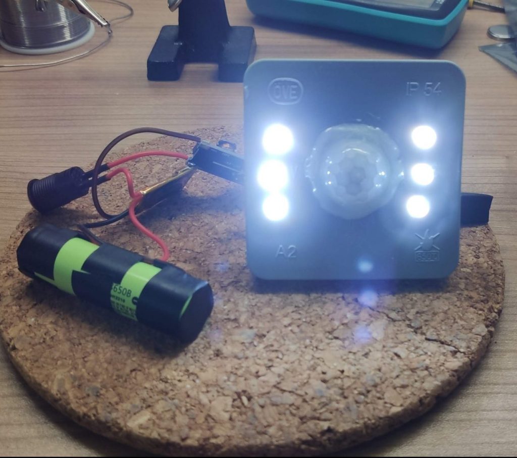
If you’re now pressing the button you should see the outdoor light LED’s light up. This is the normal calibration behavior of the HC-SR501. If the leds turn of after some time, they will not light up again until it’s dark. That’s the reason why we added the LDR to the sensor😉.
First bench test
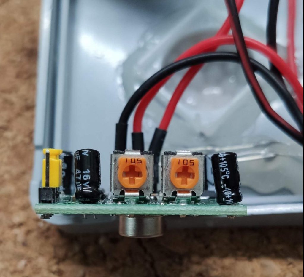
Use the two potentiometers on the sensor to adjust the sensitivity and the light duration of the sensor. Take also a look at the jumper for selecting the operation mode. In my case I set it to “repeat trigger”, that ensures that the light stays on if there is motion again during the on time of the LED’s. For more information about the configuration of the sensor, checkout the HC-SR501-datasheet .
Adjustment of the sensor
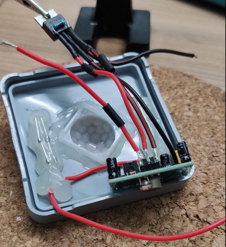
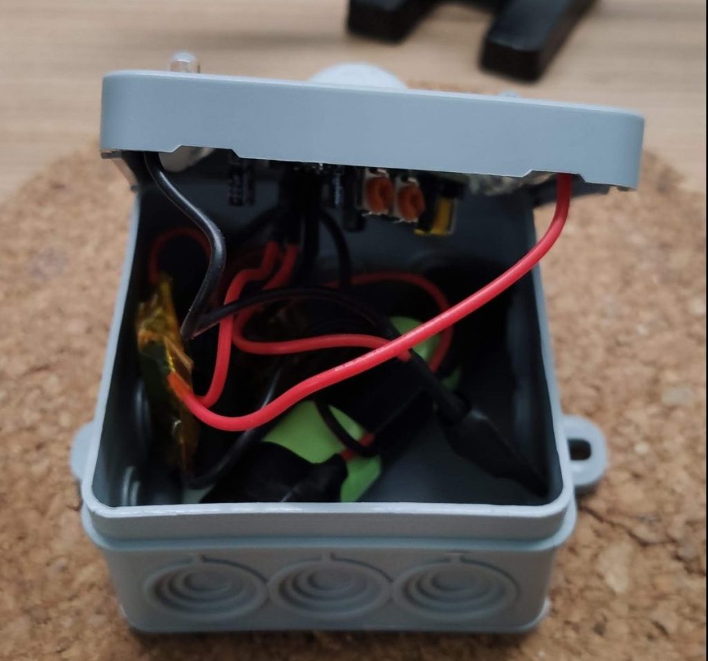
After finishing the adjustments we can squeeze everything into the electric junction box. It’s a tight fit but it worked for me.
Everything in a box
Final thoughts
And that’s it, a complete analog DIY battery powered PIR outdoor light 😊. It was so much fun to built it and I learned a lot about transistors and circuits in general. Further more, it teached me that not everything must be “smart” to be smart.
If you like this project or you already built your own version, feel free to share your results with me on twitter 🤓
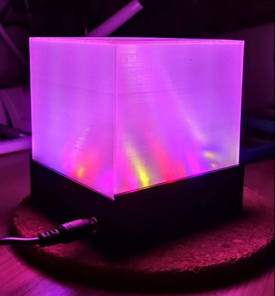
Today we’re gonna explore a basic LED light setup you can use with WLED. This kind of setup is perfect for small projects which will not handle a lot of LEDs, like our cube light. So we don’t have to care much about fusing, cable thickness and heat dissipation.
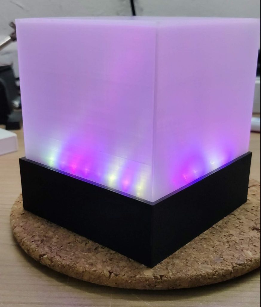
The final cube light
Parts list
For this project we will use the following components
*Some links are affiliate links. If you use them to buy the parts for your project you will help me and my next project. These links will cause no extra fee or costs to you
All components
Doing the math
Even if you’re working on a small LED light project you have to take care about electrical currents and voltages, especially if you want to power your LED’s from a plug socket like we do. So let’s answer some fundamental questions to ensure that our light cube will glow instead of blow, if we turn it on.
What voltage do we have to use?
To keep it simple, we’ll use the same voltage on all of our components. In our case, it’s 5V DC which is pretty secure in combination with low current. We ensure that all of our components use the same voltage, to prevent voltage conversion.
How many LED’s can we use?
The amount of LED’s depends on the amount of current our power supply can provide. The larger your power supply, the more LED’s we can use.
In our project we want to use 28 LED’s. To calculate how much current we will need, we have to sum up the “maximum current per LED” x “the LED amount”. This will give us the current consumption of our LED strip.
In our case, each led of the strip uses 0.06A at full power. This times the 28 gives us a current of 1.68A for the strip. If we now add 0.5A for the D1 Mini, because the controller also consumes power, to our calculation we will get the total current consumption for our cube light which is about 2.2A.
So our power supply has to deal with 2.2A if everything is maxed out. In reality it would be less because no component is perfect, but we wan’t to be super safe 😉.
What power supply do we have to use?
Our power supply has to match in two ways. In voltage and in the current. The voltage must be exact the voltage we want to use in your circuit. The provided current of the power supply can be higher but not lower, because our project will only draw as much current as it needs.
For our cube light we need 5V DC and it will draw a current of about 2.2A at max power usage. So we will use a 5V DC / 2.5A power supply.
Tip: Don’t run the power supply on max current all the time to increase the lifetime.
Prepare the cube light base
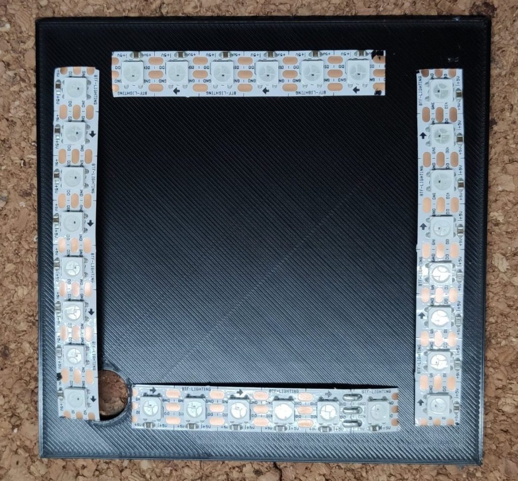
After the math we can now proceed building our cube light. We will start with the LED strip. To get a feeling of how the LED’s will fit in the case, lay them out on the sliding plate of the enclosure. The cables will start at the hole in the left down corner. Keep an eye of the direction of the strip. On the strip you will find small arrows which indicate the direction of the data signal. These arrows must point in the same direction so that the data signal for the last LED has to pass all the other LED’s before.
Layout of the LED strip
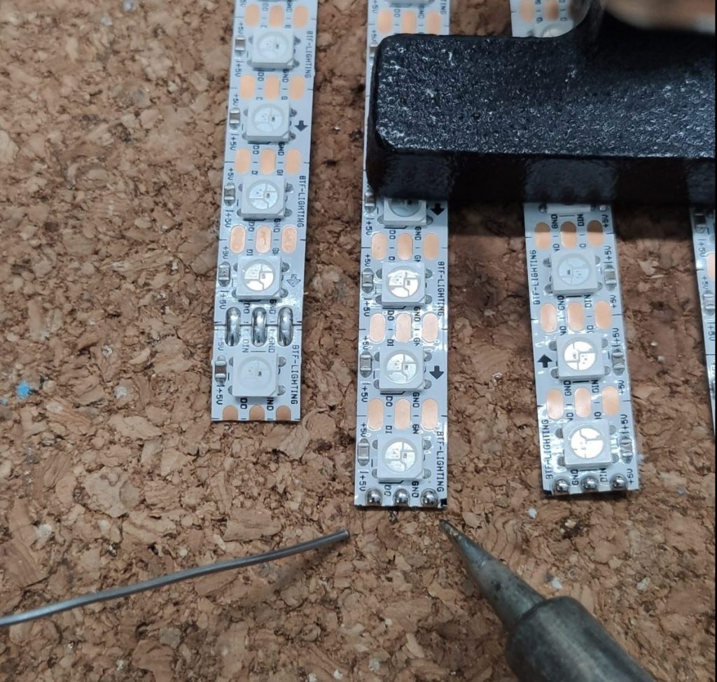
Now that we know how to layout the strip, we can start soldering it. Start with presoldering all the pads of the strip pieces. This makes wire soldering more easy later on.
Presoldered strips
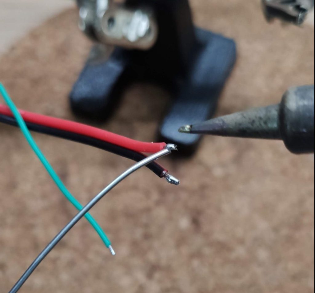
Now grab some wire and presolder the ends. Take some longer cable for the start of the strip.
Presoldered cables
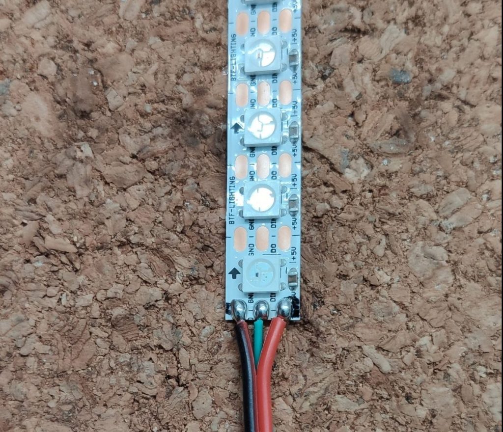
After that, solder the wires to the strip. Use red for 5V, black for GND and green for the data signal. Because we presoldered the strip and the wire we don’t need extra solder now, we just hold the wire on the pad and heat it up to get a strong connection.
Soldered strip
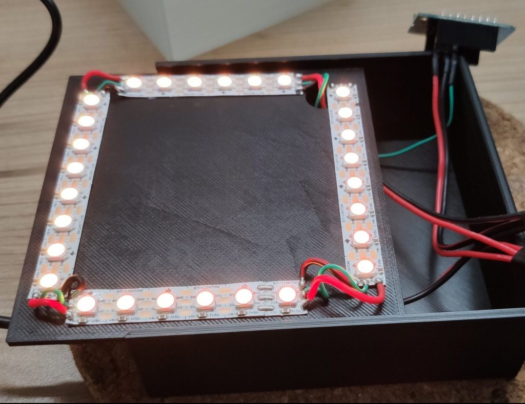
Repeat this process with all the pieces of the strip until you have the full square you lay outed before. During the soldering, check the layout couple times to ensure everything fits on the slide plate.
The complete soldered strip
Before we glue the strip to the sliding plate, we will pick our multimeter set it to continuity test mode and check if no connection is broken. Check the end against the beginning of the strip. You should get positive result on the 5V and the GND wire. Because of the LED internals, the data wire can’t be tested that way so this result will be negative.
If the tests are successful grab the sliding plate and glue the strip onto it with the double sided tape on the back.
Strip glued to the plate
Prepare the case
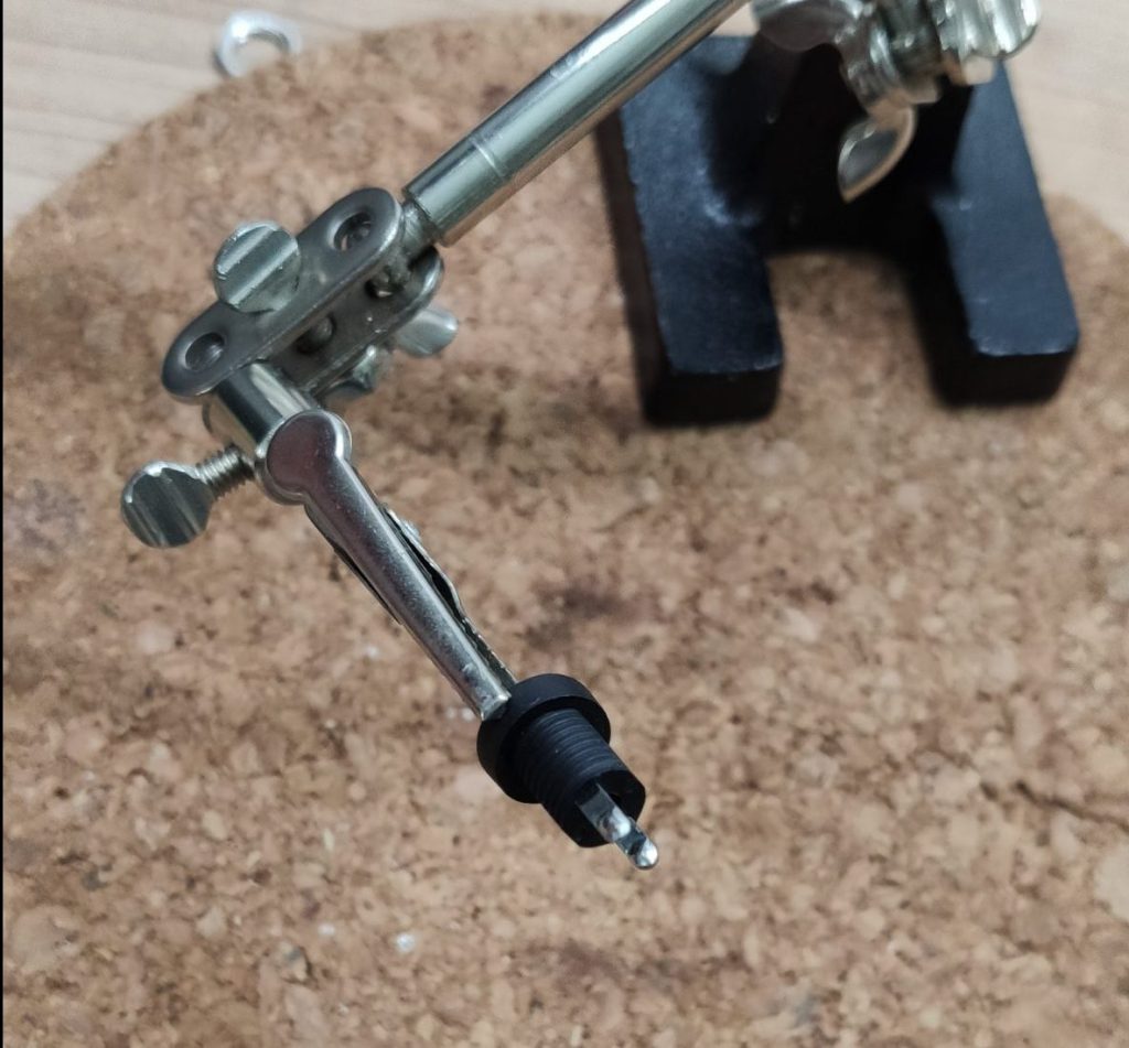
Lets now have a look at the bottom of the enclosure. This will hold the D1 Mini and the barrel-jack, in which we will plugin our power supply. Start with the barrel-jack and presolder the ends. Then check which pin is 5V for the next step.
Presoldered barrel-jack
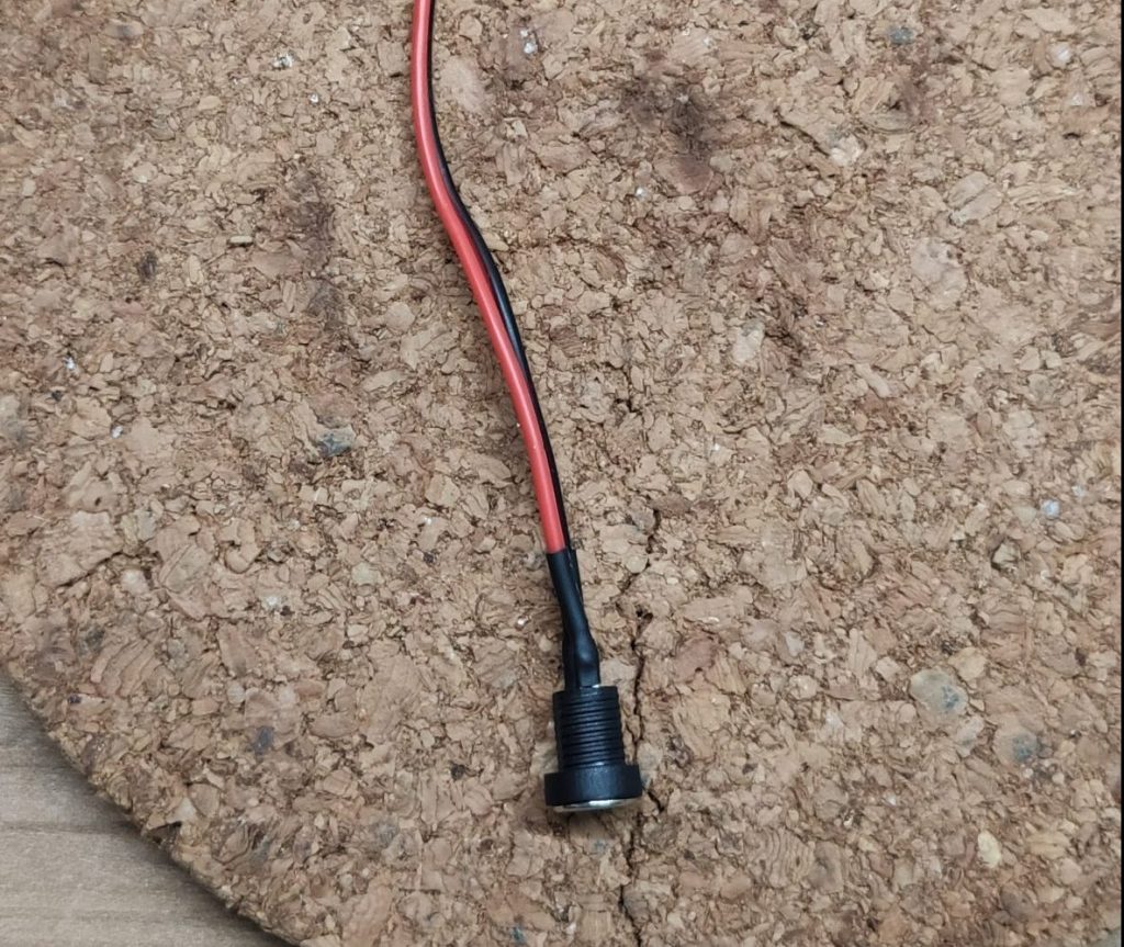
With the polarity in mind, grab some wire and solder it to the barrel-jack, use the same technique as on the LED’s strips. To prevent shorts add some heat shrinks.
The finished barrel-jack
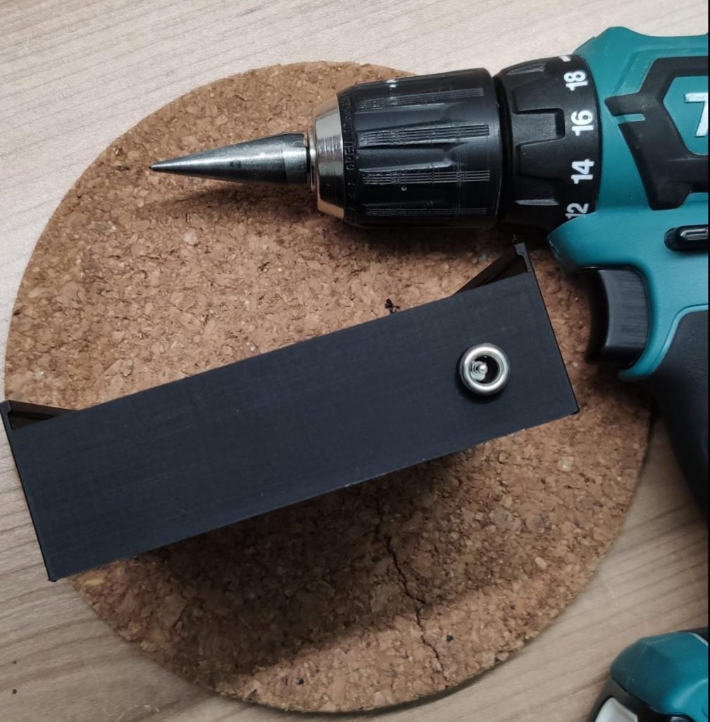
Now, flip the enclosure and drill a hole into it to mount the barrel-jack. I used a conical metal drill bit to find out the perfect size, but any large metal drill should work too. To secure the barrel-jack in the case use the screw it comes with or use some hot glue.
The prepared enclosure
Prepare the D1 Mini
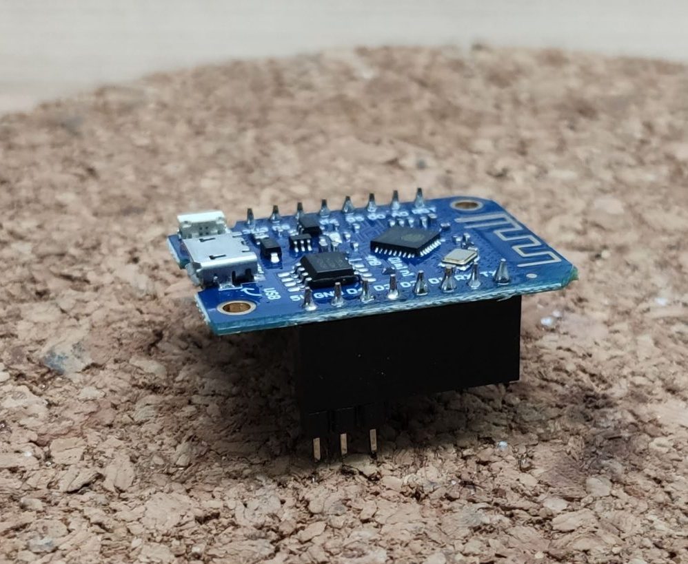
Let’s focus on the D1 Mini and the wiring we need to connect it to the LED strip. If you order a D1 Mini, it will come mostly unsoldered, so you have to solder some kind of pins to it. In my case I had a soldered one laying around, so I used that for the cube light. Besides of the D1 Mini you also need three male pins, two for power and one for the data connection.
D1 Mini with pins inside
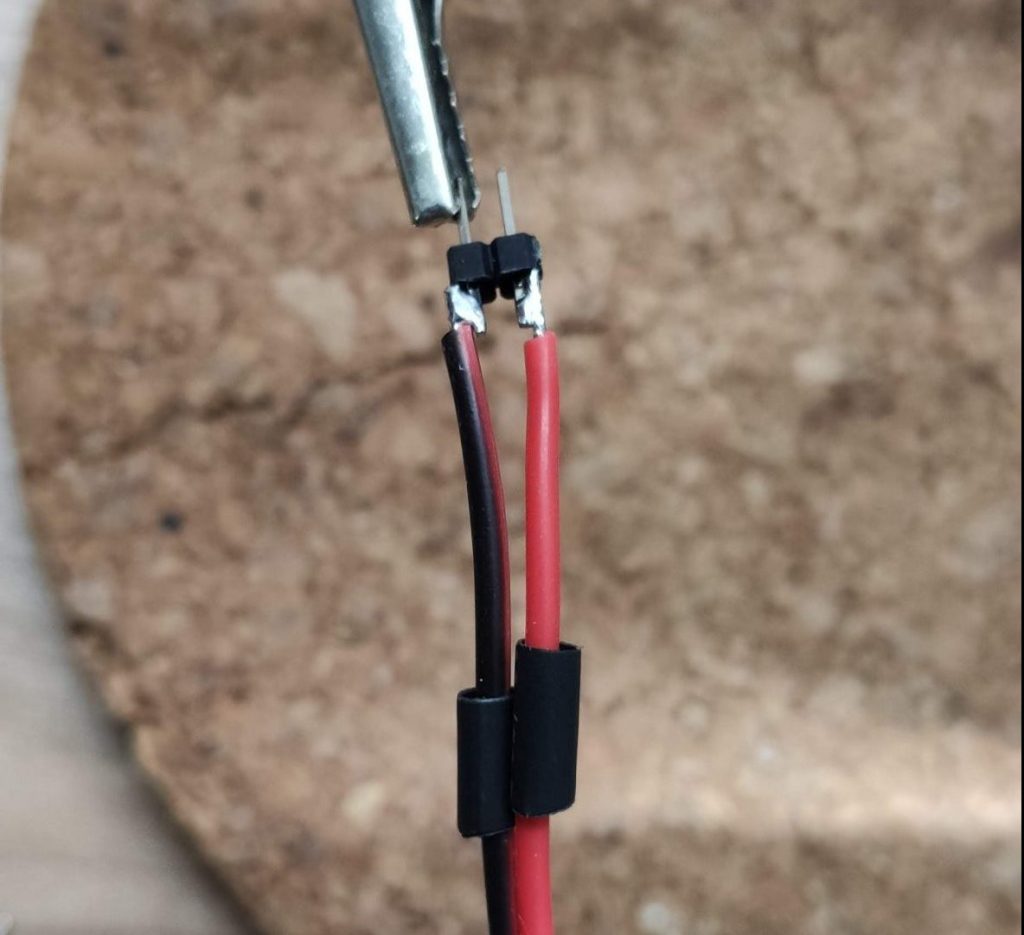
If your D1 Mini is ready to go, take two of the three male pins and solder them to a piece of wire. These two pins will be used to power the D1 Mini with 5V. Don’t forget to add heat shrinks to prevent shorts.
D1 Mini power cable
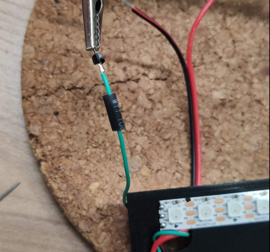
Now grab the third pin a solder it to the green wire of the LED strip. This cable will transfer the data which will tell our LED’s in which color they have to light up.
The data cable pin
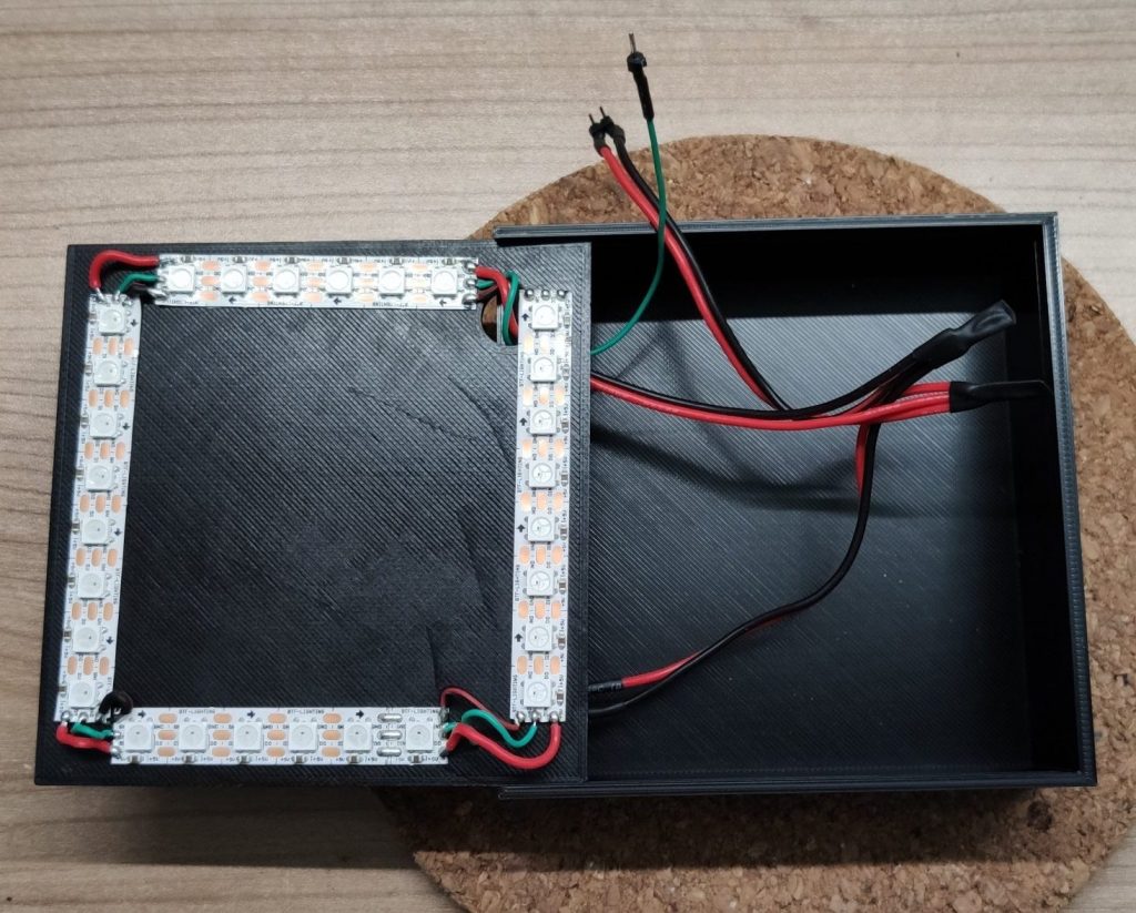
Assemble the base
We can now finish up our assembly by soldering all the wires. So slide in the plate into the base and solder all the red and black cables together. This will connect the LED strip and the D1 Mini to the barrel-jack. As same as before, to protect the solder joints use some heat shrinks.
The complete base
Install WLED
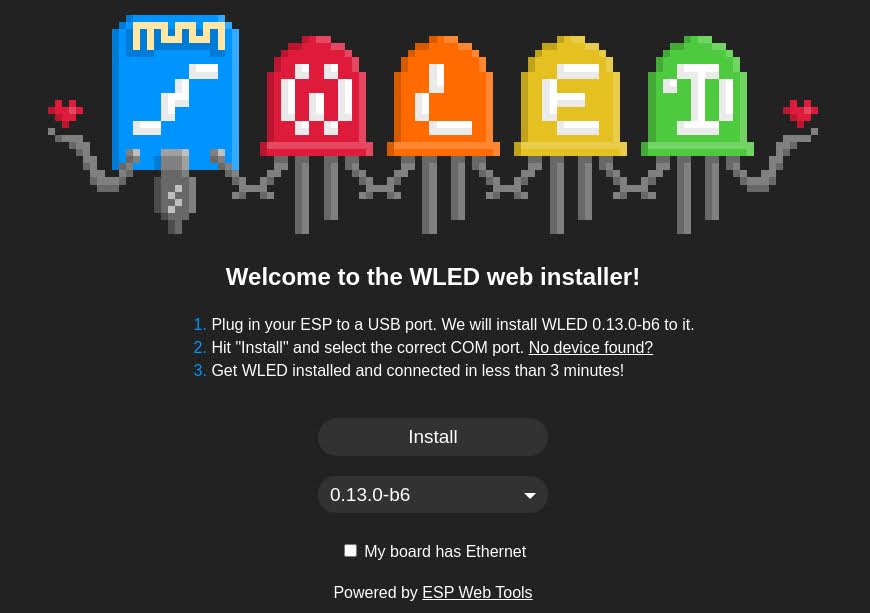
Next up we will program the D1 Mini. So hook it up to micro USB cable an plug it into your PC. Open a Google Chrome based browser and go to the WLED Installer Page.
WLED install page version 2
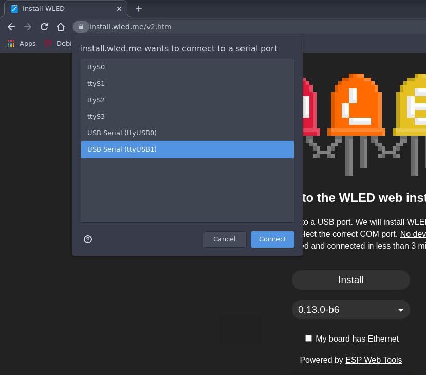
Click on the install button and select your USB device which the D1 Mini is connected to. If your device does not show up you might need to install an additional driver. If so, please try to install the CP210x or the CH341 driver and retry this step.
Connect your device
You have now to confirm that you really want to install WLED on the D1 Mini. After that, the installing process starts.
Installation process
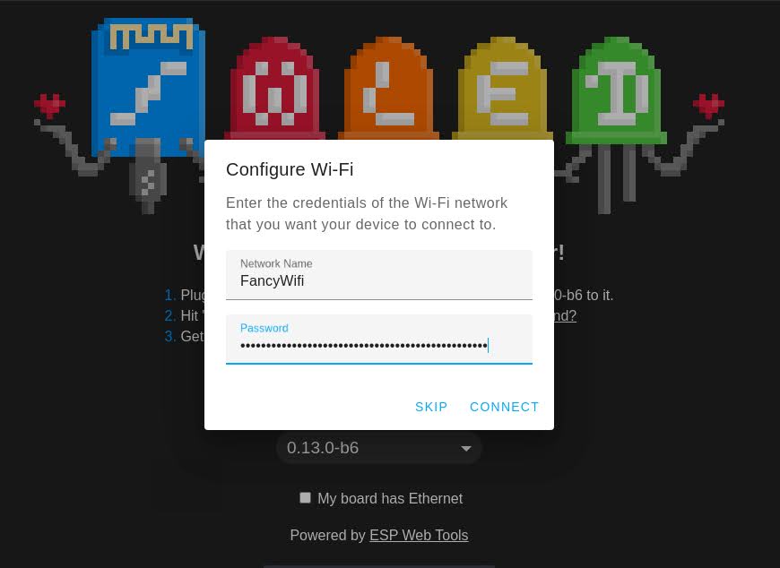
After the installation has completed, click “NEXT” and enter your WiFi credentials. This will add WLED to your home network.
Add WiFi credentials
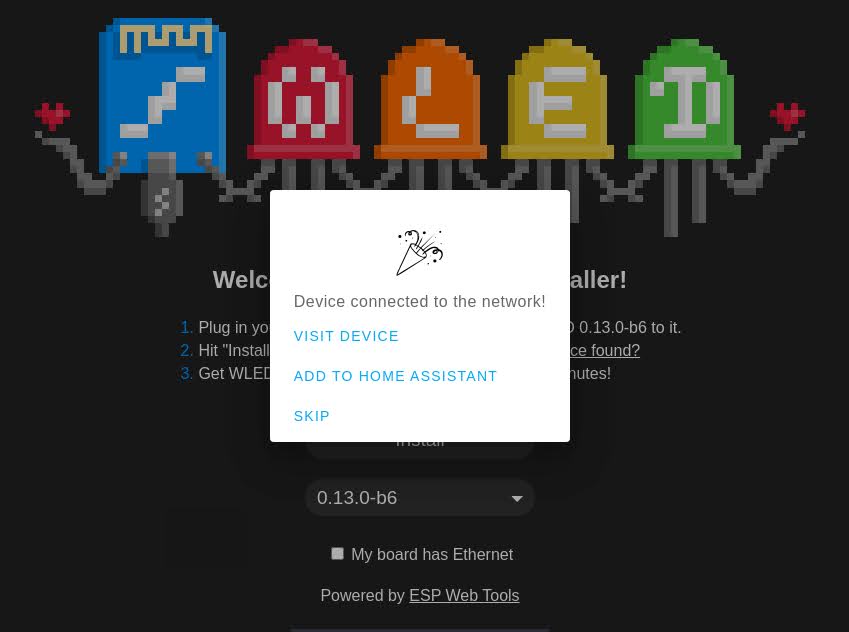
You are now able to browse the WLED software in the browser. To jump to the main page, just click “VISIT DEVICE”. From that point, you can also find the device in the WLED App, which is available for Android and IOS.
Installation successful
Configure WLED for the cube light
Because WLED very versatile, we have to adjust a few settings to make it work for our LED project.
We will adjust:
The type of the strip
The LED count
The LED data pin
The power settings
Navigate to the main page of WLED and click on the config icon to enter the configuration menu. After that, click on “LED Preferences” to enter the “LED & Hardware setup”.
Got to “Config”
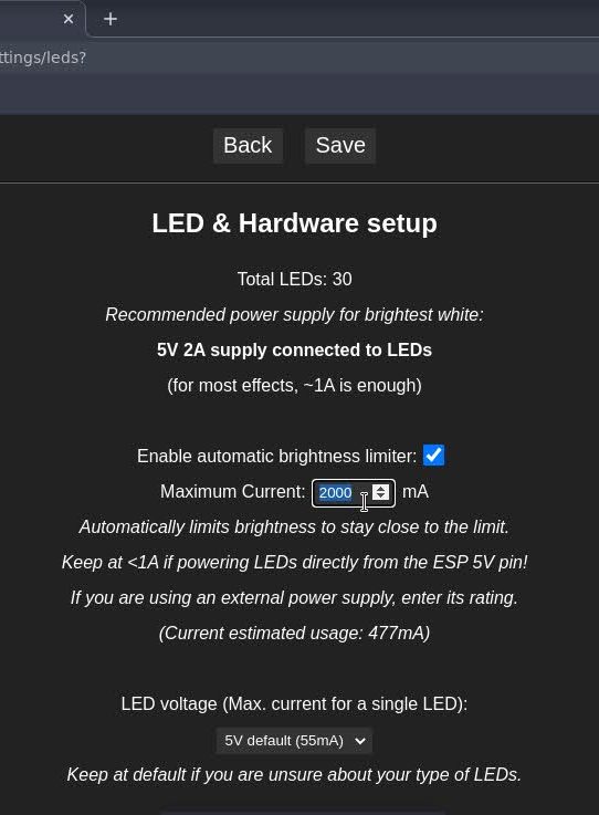
We will now adjust all the required settings. First, change the “Maximum Current” value and set it to 2200mA. This is the value we calculated as we did the math. These setting prevents that our cube light will draw to much current from a software side.
Brightness limiter
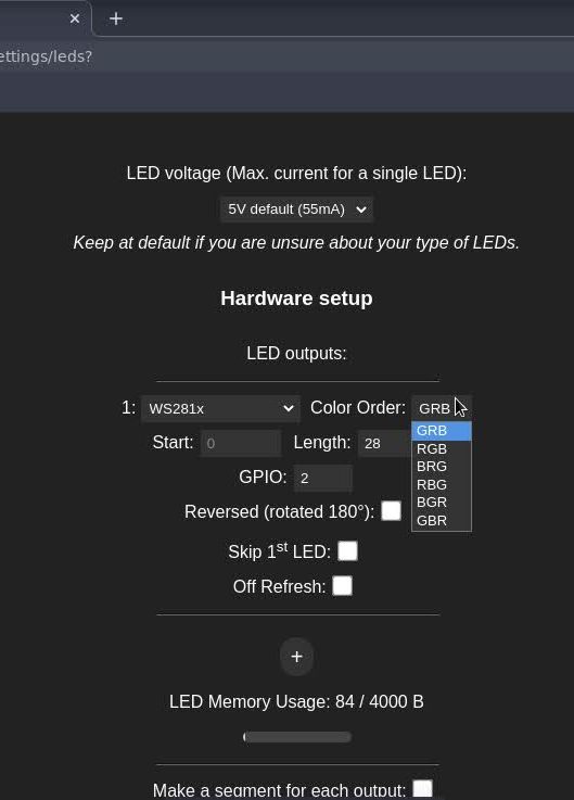
Then scroll down to the Hardware setup to change the LED details. Just follow the list below.
Todo list
Check the type of the LED strip: WS281x
Check the Color Order: GRB
Adjust the length of LED strip: 28
Set the GPIO pin for the data signal: GPIO 2 ( marked as D4 on the board)
Configure the LEDs
Light it up
After installing and configuring WLED, we will put in the D1 Mini back into the base of our cube light. Unplug it from the PC and put into the base. Connect the red / back cable to 5V / GND and the green cable to D4. Double check the 5V and GND connection before power it on.
The connected D1 Mini
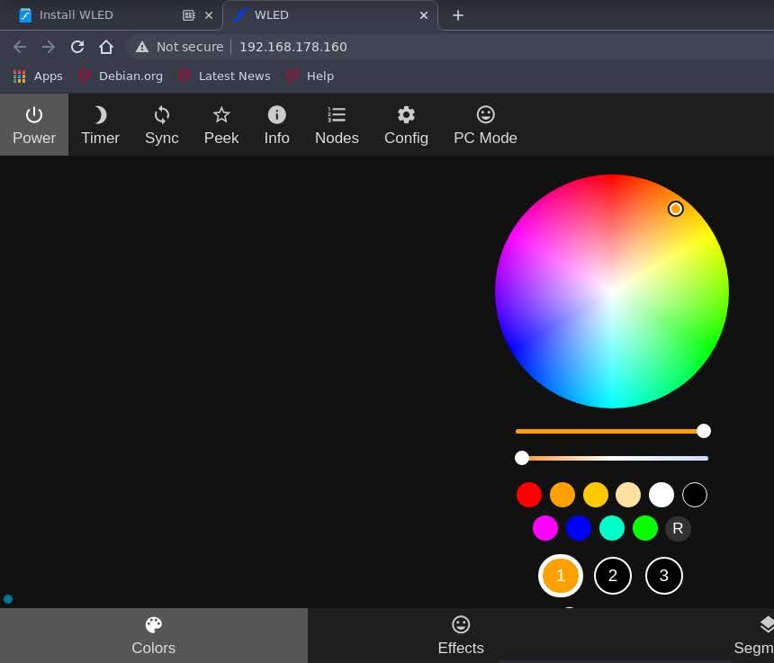
We can now bench test the cube light. If we plugin the power supply, the LED strip should light up in” WLED orange”. We can also browse the WLED software and start changing the colors and effects.
Bench test the light
Last not least, put the transparent cube on top and enjoy the beautiful cube light.
Your awesome cube light
Sum up
Yeah! 🤩 That’s it, we’re done! We build an awesome light and learned the basics of LED projects, like power calculation, LED strip orientation and WLED configuration. And that’s only the tip of the ice berg. You can do much more with LED’s and the WLED software, like matrices, sound reactive lamps or syncing effects over multiple WLED instances.
I hope you enjoyed this project as much as I did. If you want, feel free to share a picture of your cube light or the link of this post.