If you dive in to the deep ocean of 3D printing, you will face the situation of storeing your filament in a proper way sooner or later. To be more precise, you want to keep your filament as dry as possible because most filaments absorb moisture. If you store your filament in a large box like I do, the humidity value in that box is kinda important. That was exactly the motivation behind this diy project. Of course, that’s not the only case for such a sensor. You can use it in many different scenarios where the humidity and or temperature value becomes important 😉.
The Idea
I wanted to create a relatively small sensor, which is battery powered, rechargeable and can be easily integrated into Home Assistant. After some research, I decided to go with the following setup. A simple ESP8266 (D1 Mini) including a battery shield in combination with DHT-11 humidity & temperature sensor. This setup can be easily driven by an ESPHome sketch and seamlessly integrated into Home Assistant. It’s also small enough to fit into a small container which, in my case, was originally made for hair gel.
Parts list
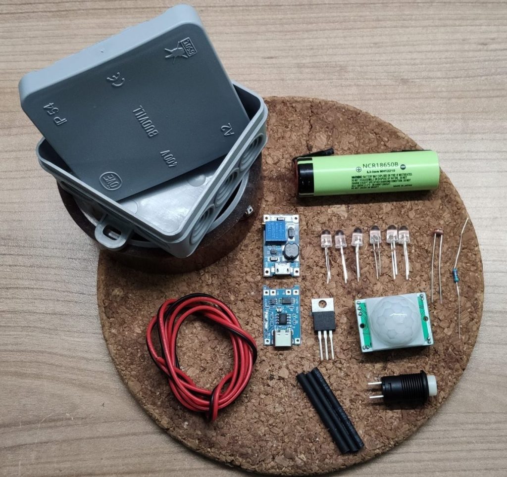
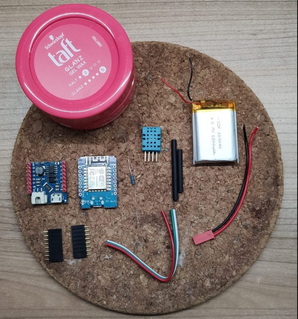
For this project we will use the following components:
- A D1 Mini
- A D1 Mini Battery shield
- Female pin headers (mostly included with the D1 Mini)
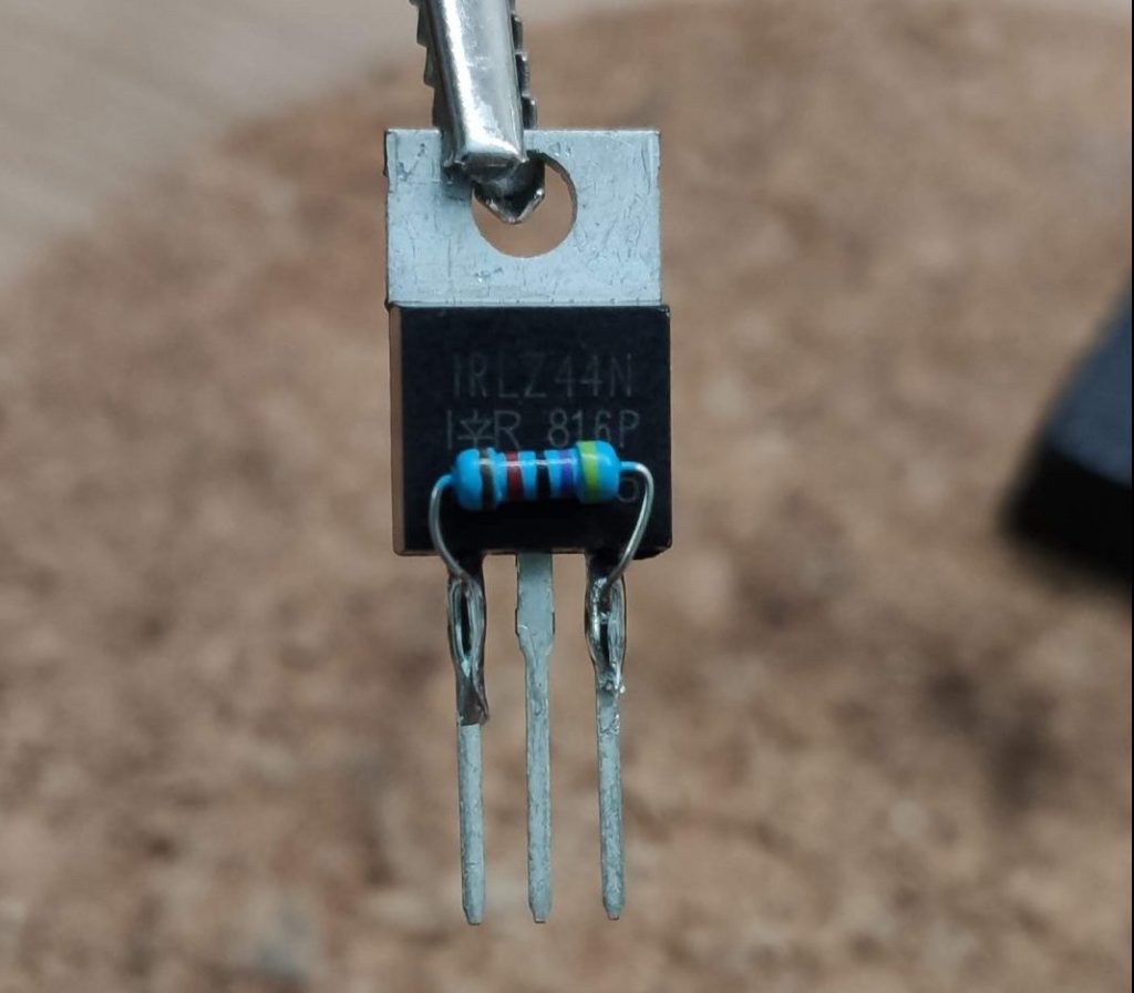
- One 100K Ohm resistor
- A DHT-11 temperature and humidity sensor
- Some heat shrink
- A 3.7V Lipo battery
- A battery connector cable (optional, because you can solder the battery to the battery shield)
- Some wires
- A container / something similar as housing (I used a old hair gel box)
*Some links are affiliate links. If you use them to buy the parts for your project you will help me and my next project. These links will cause no extra fee or costs to you
Prepare the D1 Mini
Start with soldering the female pin header to the D1 Mini. Mostly the D1 Mini comes with a variety of pin headers, select the female ones that fits best. Solder the pins to downside of the D1 Mini so that the WIFI antenna isn’t blocked by the battery shield if it’s connected.
Prepare the battery shield
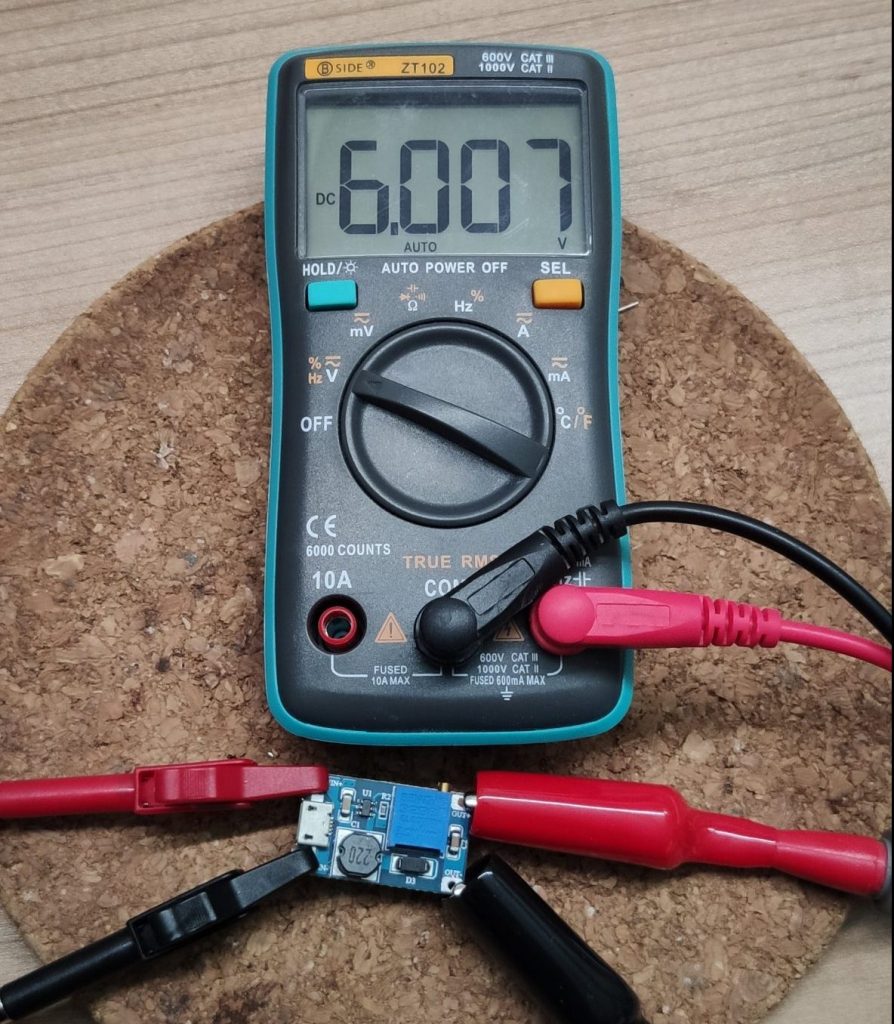
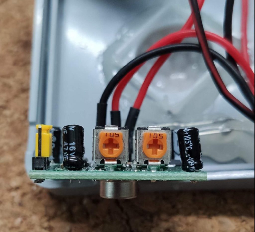
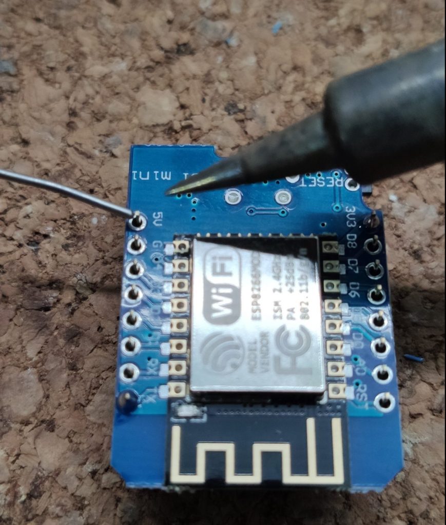
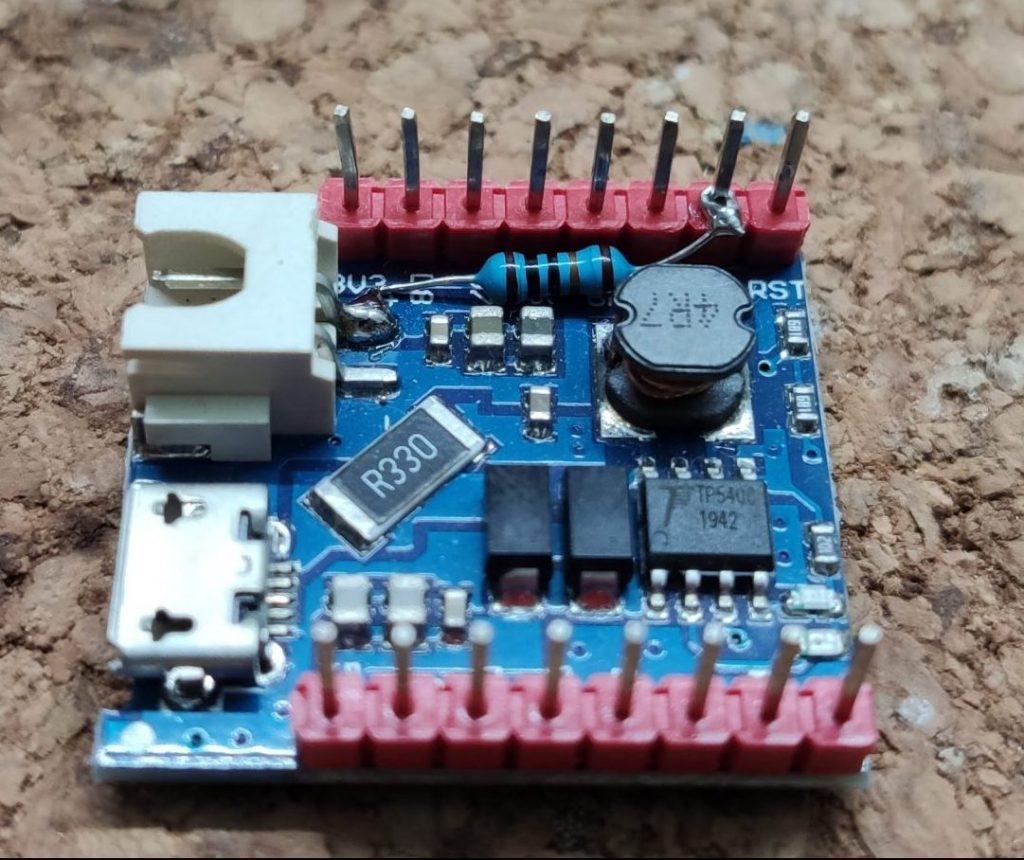
The battery shield will provide the power for the D1 Mini and will also take care of the battery charging process. That’s pretty neat, but with a slight modification, we can make the board even more useful. If you add a 100K Ohm resistor between the plus pole of the battery and the analog A0 pin, you can read the battery operating voltage, which can be used to calculate the capacity of the battery. With that value, you can create an automation in Home Assistant, to inform you if the sensor needs to be recharged.
Prepare the DHT-11
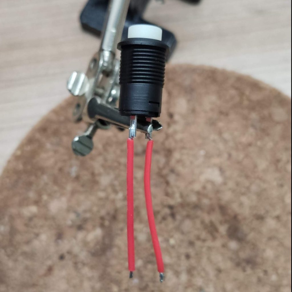
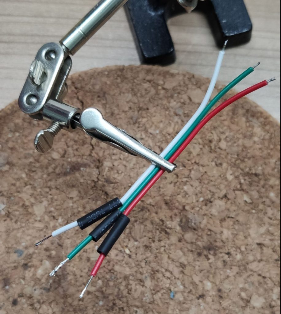
To connect the DHT-11 sensor to the D1 Mini grab some wires and presolder the ends on one side. Next snip of some heat shrinks and slide them over the soldered wires.
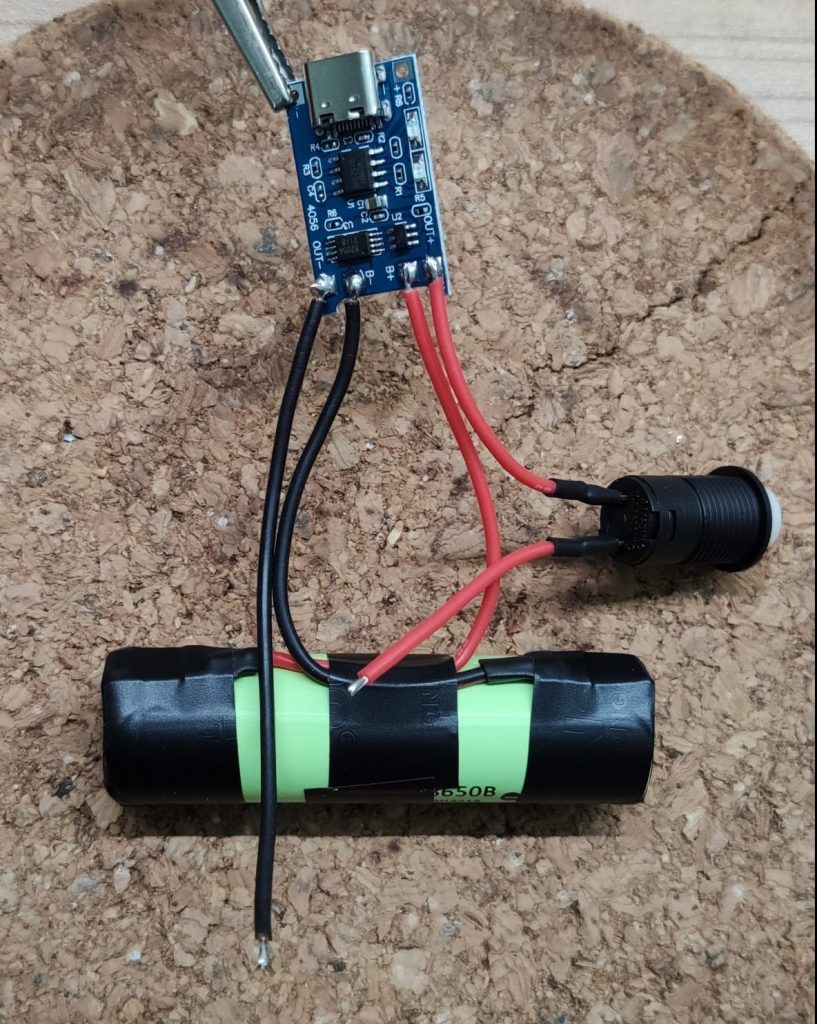
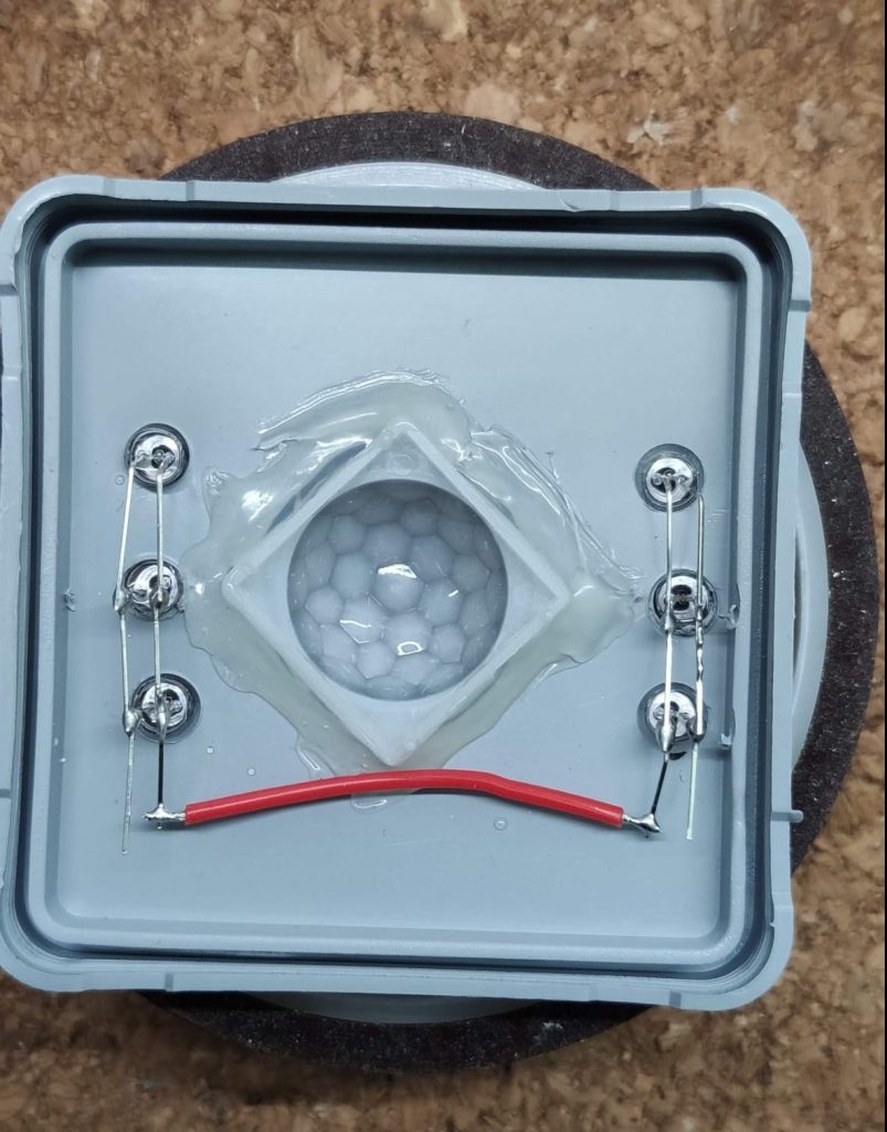
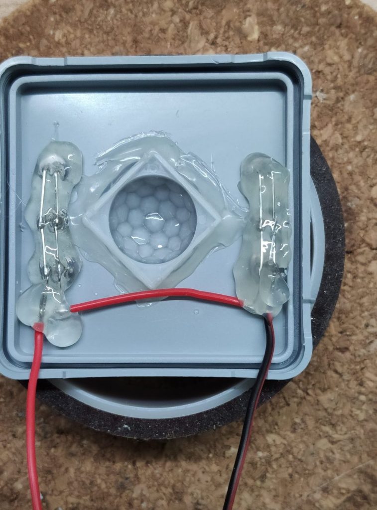
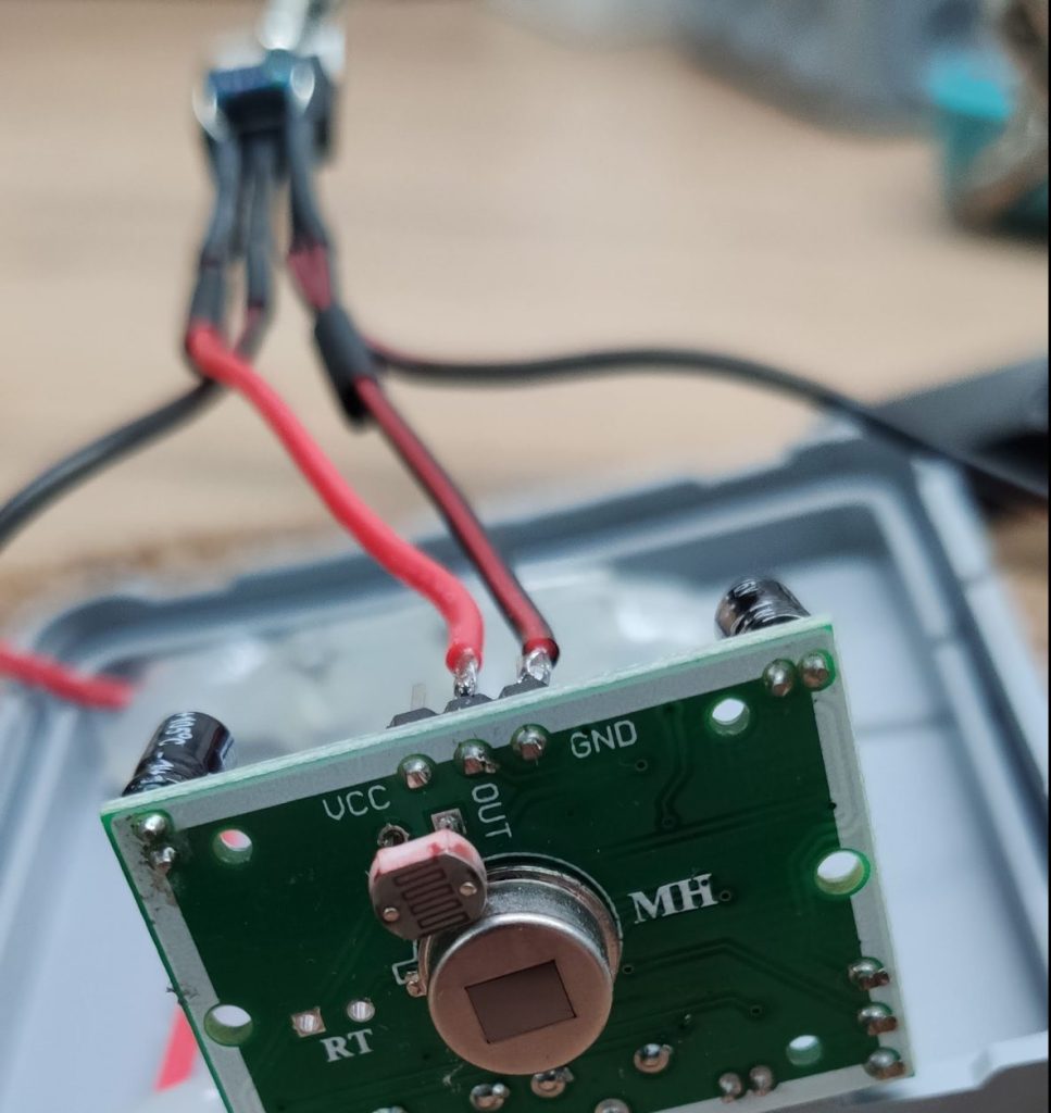
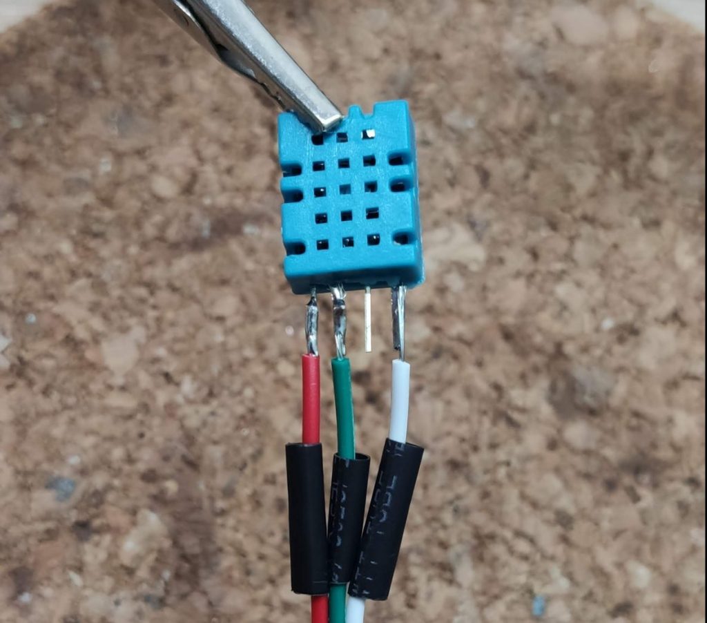
In the next step we will solder the wires to the DHT-11. The DHT-11 has 4 pins in general where the third one f.r.t.l isn’t in use. Solder the wires to DHT-11 as shown on the picture. I used red for positive, white for GND and green as the data wire.
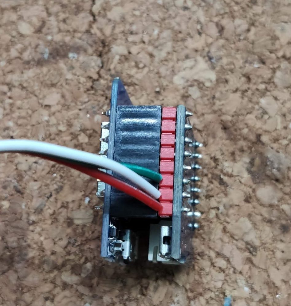
Make a Sandwich😉
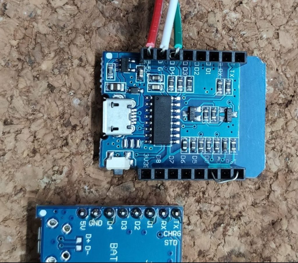
In this step we will connect the sensor to the D1 Mini and the battery shield. So flip the D1 Mini and slide the sensor wires into the females pin header. White goes to the GND pin, red to the 5V pin and green to the D4 pin of the D1 Mini. Further we will connect the RST pin with the D0 pin.
Connecting RST and D0(GPIO16) is very important, because our sensor will run on battery and not be continuously on. That would consume too much power and the battery would be empty within one or two days. To prevent this, our sensor will use a feature called deep sleep. With this feature enabled, the D1 Mini will only wake up every couple hours, take some measurements, send the data to Home Assistant and fall back into sleep / energy saving mode. This way is super efficient and will max out the battery life up to two weeks instead of two days. To enable deep sleep on an ESP8266 device you have to bridge these two pins, otherwise the D1 Mini will never wake up again.
If everything is setup properly, connect the battery shield and the D1 Mini. Keep an eye on the pins, the labels on the battery shield must match with the ones on the D1 Mini.
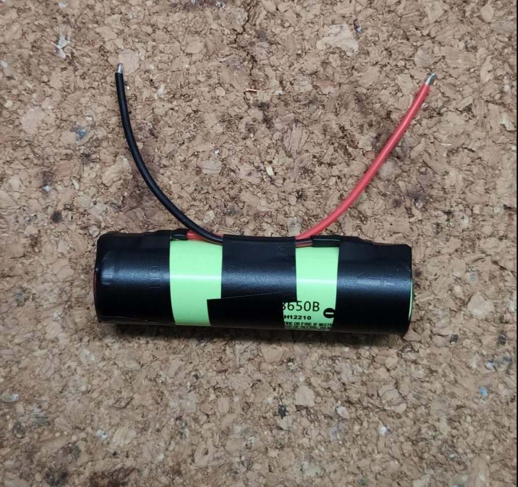
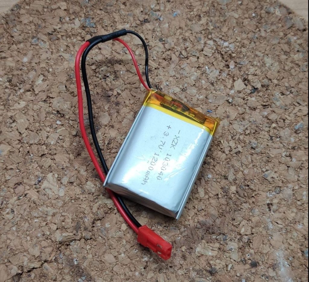
Prepare the battery
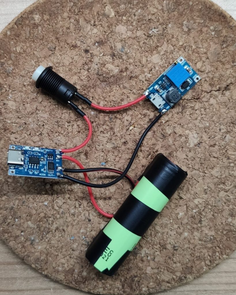
Before we flash the D1 Mini with our sketch, we will prepare the battery to our sensor. If you don’t have a connector, you can simply solder the wires to the battery socket of the D1 Mini battery shield. In my case, I had a spare connector lying around, so I soldered it to the battery to make disconnections simpler. It’s also recommended to disconnect the battery from the D1 Mini while flashing. If you don’t use a connector, you have to disconnect the D1 Mini from the battery shield for the flashing process.
Flashing the D1 Mini
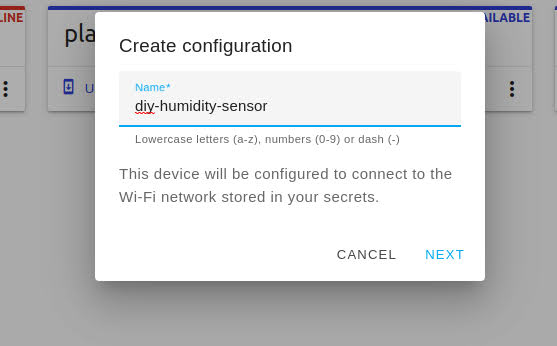
To flash the sketch to your D1 Mini, go to the ESP Home section in your Home Assistant installation and create a new project and start with a project name. I named mine diy-humidity-sensor.
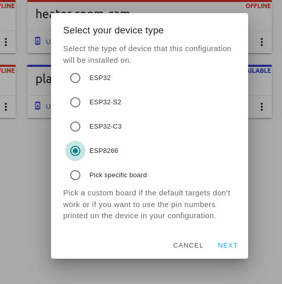
Next choose the board type. Because we are using a D1 Mini click on ESP8266.
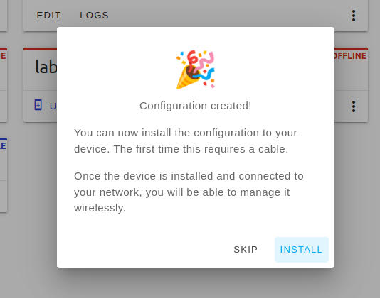
After that click on next and then on install to choose a preferred installation method. I always use the manual download option because I like to flash my ESP’s using ESP Home Flasher.
Install the sketch
To finish the installation, copy the script below to your editor, compile it and flash it to the D1 Mini. If you don’t use secrets, change the WIFI credentials to your needs. This sketch will create several sensors in Home Assistant including the battery percentage one. Further it will use the deep sleep function to operate 1 minute and then goes into sleep for 3 hours.
esphome:
  name: diy-humidity-sensor

esp8266:
  board: d1_mini

# Enable logging
logger:

# Enable Home Assistant API
api:

ota:
  password: "SuperSecr3t"

wifi:
  ssid: !secret wifi_ssid
  password: !secret wifi_password

  # Enable fallback hotspot (captive portal) in case wifi connection fails
  ap:
    ssid: "Diy-Humidity-Sensor"
    password: "SuperSecr3t"

captive_portal:

sensor:
#VCC on batter
  - platform: adc
    pin: A0
    id: "LIFEPO"
    name: "A0 voltage x 3.0"
    update_interval: 18s
    accuracy_decimals: 3
    filters:
      - multiply: 3.0
  - platform: template
    name: "diy-humidity-sensor-battery-voltage"
    unit_of_measurement: 'V'
    update_interval: 18s
    accuracy_decimals: 2
    lambda: |-
      return (id(LIFEPO).state);
  - platform: template
    name: "diy-humidity-sensor-battery-percentage"
    unit_of_measurement: '%'
    update_interval: 18s
    accuracy_decimals: 0
    lambda: |-
      return ((id(LIFEPO).state-2.2) /0.8 * 100.00);

#Temperature and humidity
  - platform: dht
    model: DHT11
    pin: D4
    temperature:
      name: "diy-humidity-sensor-temperature"
    humidity:
      name: "diy-humidity-sensor-humidity"
    update_interval: 18s

deep_sleep:
  id: deep_sleep_1
  run_duration: 60s
  sleep_duration: 180min
Finish the installation
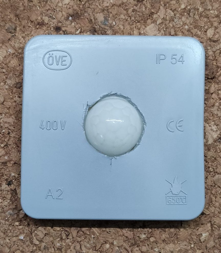
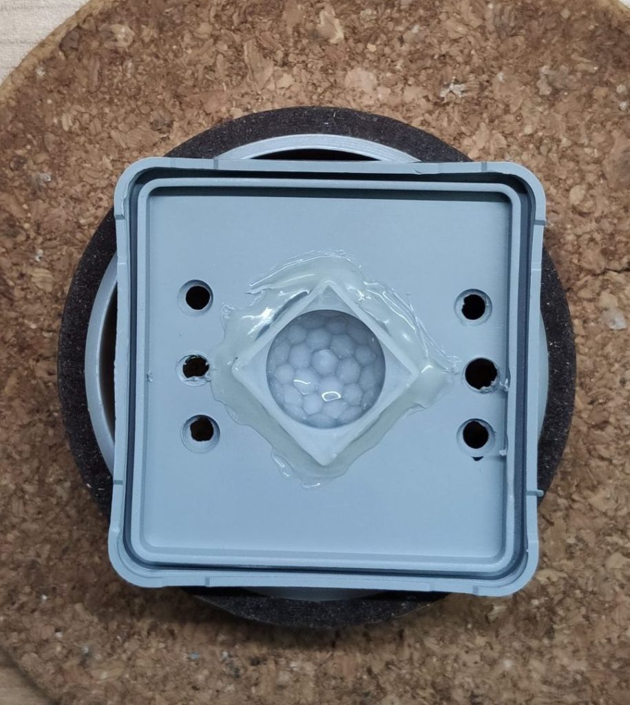
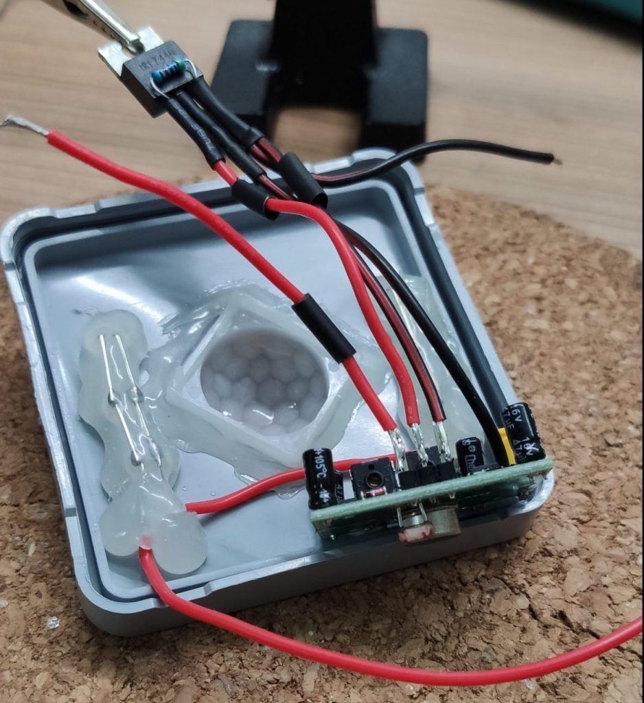
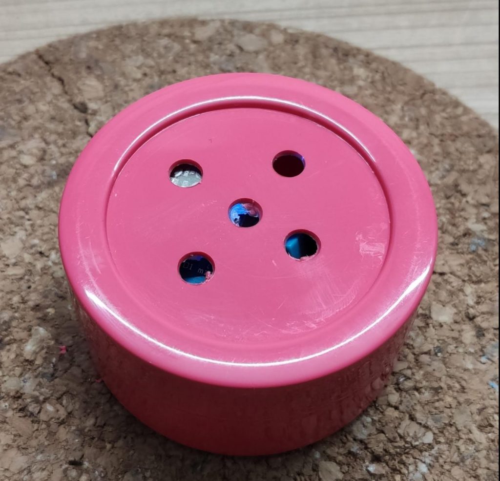
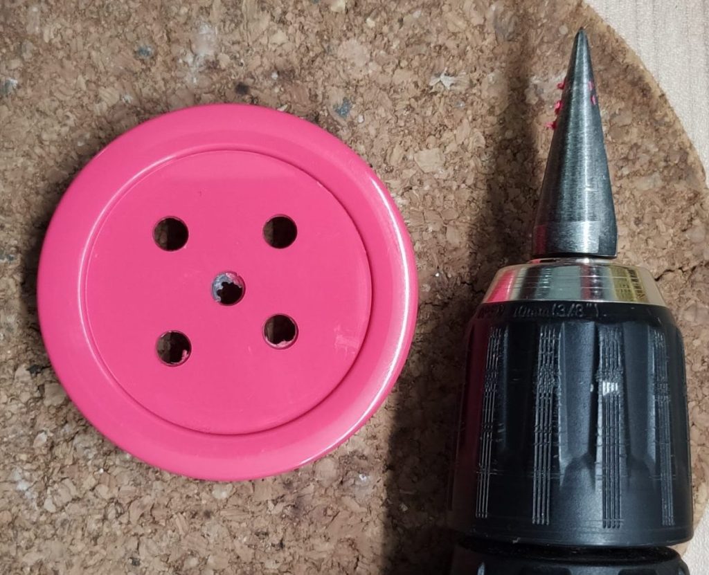
After flashing the D1 Mini, grab your enclosure and ensure that the DTH-11 will be exposed to the air. I drilled some holes into the lid of my container to ensure that.
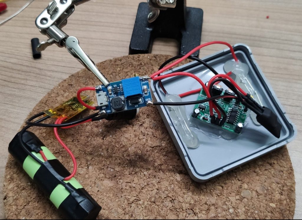
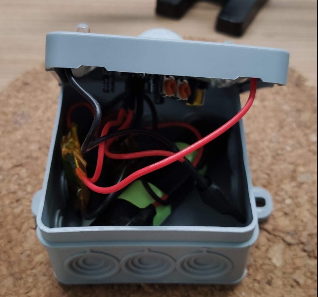
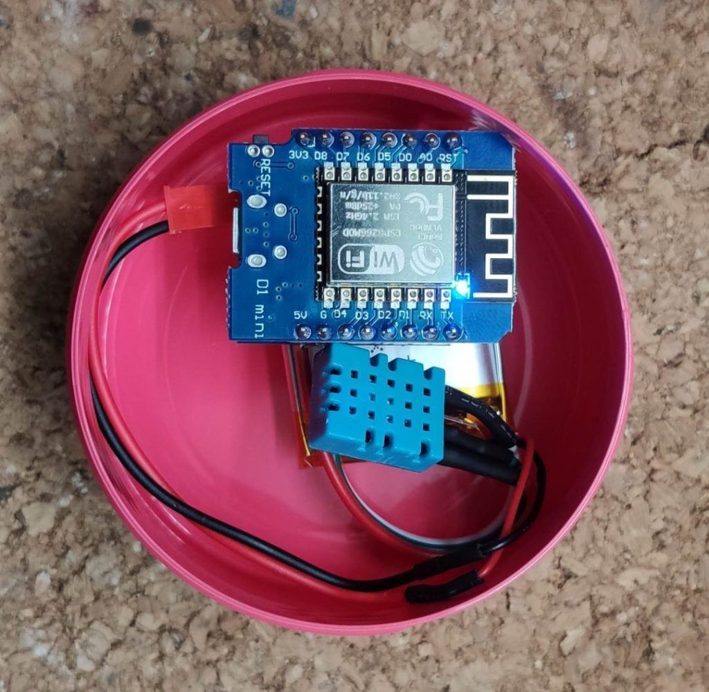
Last not least connect the battery to the battery shield and place everything inside the container.
UPDATE: During my tests, I found out that the LED on the D1 Mini uses a quite large amount of power. This will decrease the run time of the sensor, so I desoldered the LED from the D1 Mini 😬.
Check Home Assistant
After connecting the battery to the sensor, you will find a new ESPHome device in Home Assistant which provides the sensors, which were defined in the sketch.
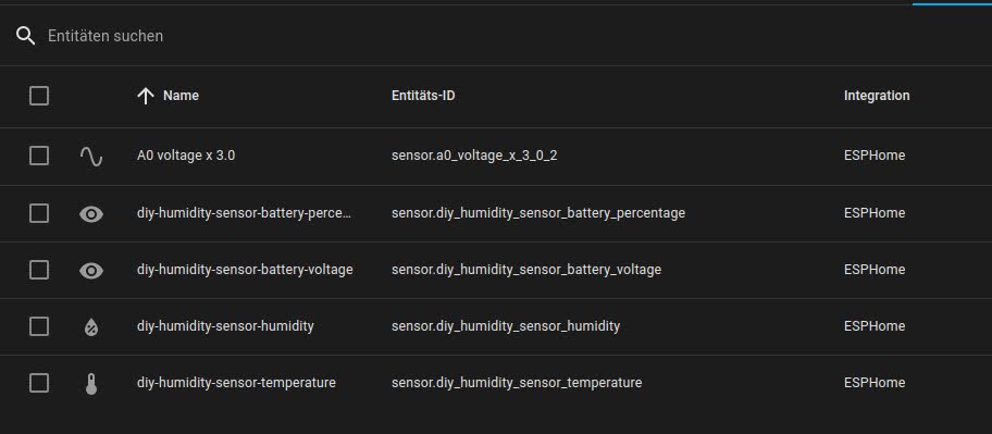
These entities can simply added to a dashboard or used in an automation.
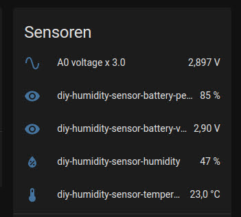
Sum up
And that’s it. Your diy filament humidity sensor is ready to go 😁 You can now measure the current humidity and temperatue inside you filament storage. You can also use the sensor data in an automation which informs you if the humidity in your filament storage increases or exceeds a certain level. Or you can display the information on a dashboard like I did.
I hope you like this project and I’m looking forward to your comments and shares.