
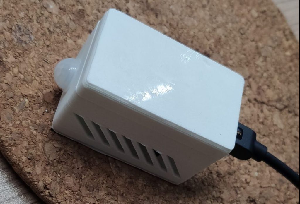
In this project we’ll build a DIY Multi sensor which can recognize motion and measures the current temperature / humidity in the room. The brain of the sensor will be a D1 Mini (esp8266) which uses the tasmota firmware to collect all the data, hooks into your local WIFI and send them to Home Assistant.
Parts list
In this project we will use the following components
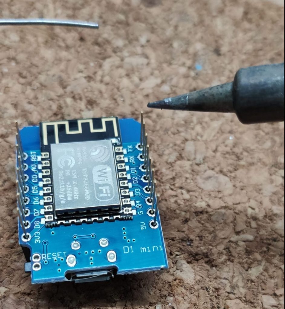
- One D1 Mini (esp8266) incl. long pins
- An DTH11 temperature / humidity sensor
- A AM312 PIR sensor
- A 3D printed enclosure from thingiverse
- Couple 0.8mm wire
- Some heatshrinks
- Hot glue

Wiring up the components
First of we will solder the long pins to the D1 Mini. I chose the long variants because both sensors will use 5V and GND from the same pins. Using long pins makes the wire soldering easier later on. Alternatively you could crimp your own dual dupont cable to power both sensors, but i.m.h.o soldering works much better for a solid connection.
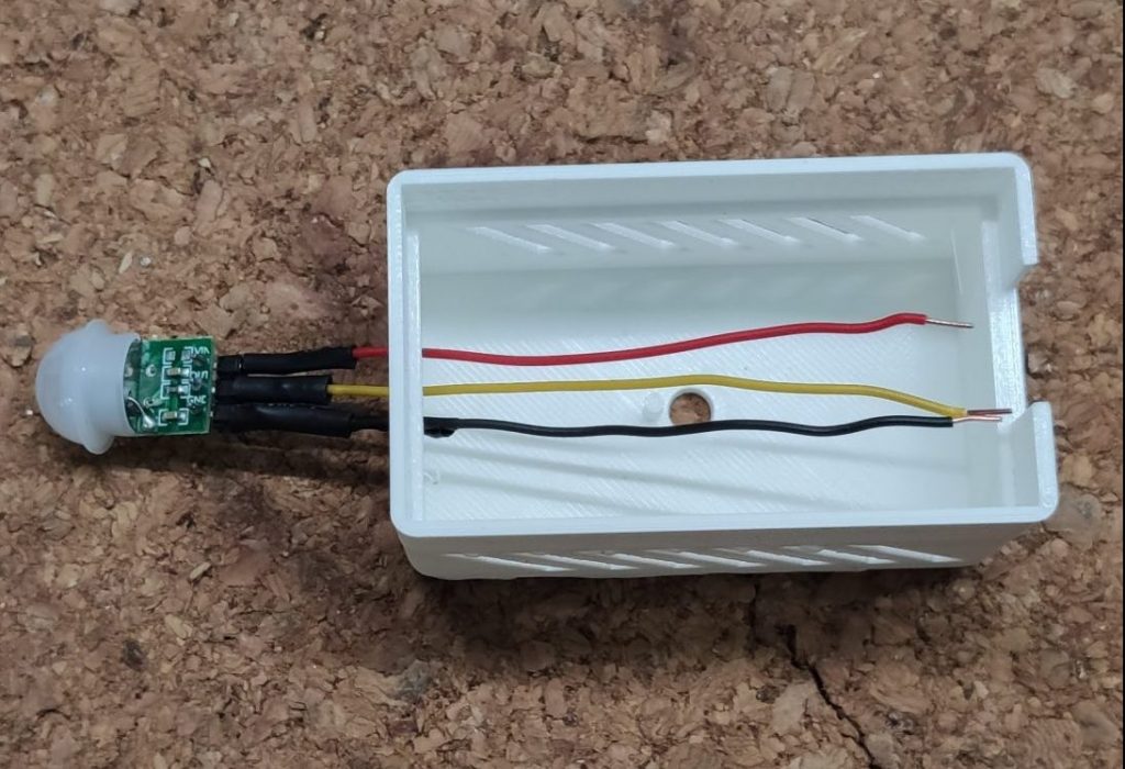
Second, we’ll solder the wires to the sensors. I my case, I used black for GND, red for 5V/VCC and yellow as the data wire. Double check the pins on the sensors, e.g. mixing GND and VCC will destroy them immediately. The AM312 should have markings on the board to identify the pins. The DTH 11 doesn’t so check the sensor description or take a look at my pinout on the picture.

After preparing the sensors we’ll solder them to the D1 Mini. Watch out that the wires of AM312 must be run to the enclosure first, because the sensor is mounted outside in not inside out.
We will solder the wires as follows to the D1 Mini:
- Both sensor 5V / VCC to the 5V pin
- Both sensor GND to the GND pin
- The data wire of the AM312 goes to pin D1 (GPIO05)
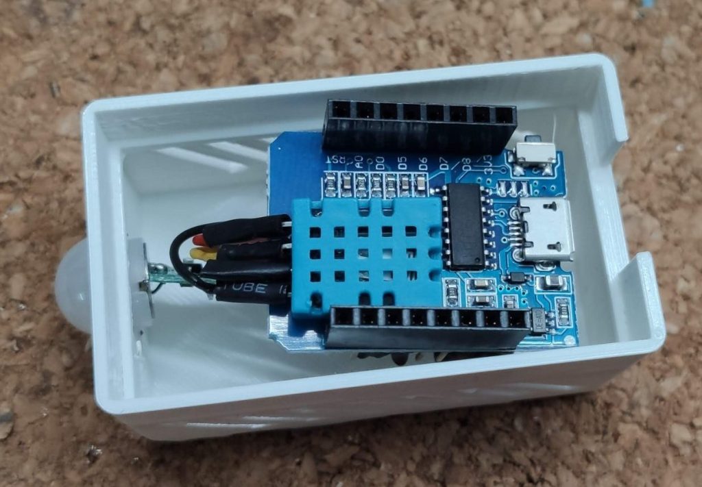
- The data wire of the DTH11 goes to pin D2 (GPIO04)
Also ensure to add a couple heatshrinks and some hotglue to prevent a short circuit inside the enclosure.

Last not least we will place all components into the enclosure, add a drop of glue to hold the AM312 in place and hook up a micro USB cable to connect everything to our PC.
Installing Tasmota
After finishing the wiring we’re now able to flash the Tasmota firmware on the D1 Mini to connect it with Home Assistant and your MQTT broker.
First, plug in your multi sensor using a USB cable with data wires in it, open the Chrome/Chromium Browser, go to the Tasmota installation page and simply click “connect”

Second, select the USB port your device is connected to and click “connect”. If your device does not show up you might need to install an additional driver. If so please try to install the CP210x or the CH341 drivers and retry the step.

After that go to the wizard, wait until Tasmota is installed on the D1 Mini. If the installation finishes successfully, your D1 Mini will spawn a WiFi-Access point called Tasmota_XXX.

Connect to the access point and go to the IP 192.168.4.1. Enter your WiFi credentials to add your multi sensor to your home network. Please keep in mind, that only 2.4GHz networks are supported.

Configuring Tasmota
If the device is connected its time to configure the multi sensor the way we want it. Open the IP address in your browser and configure the device as follows:
1. Click on “Configuration” => “Configure Other”
- Enable MQTT and the HTTP API
- Give your device a proper name
- Click save

2. Click on “Configuration” => “Configure MQTT”
- Add your MQTT IP and credentials
- Change the topic to something more useful
- Click save

3. Click on “Configuration” => “Configure Module”
- Select the module type generic
- Click save
- Click again on “Configuration” => “Configure Module”
- Select “Switch” on the entry D1 with the number 1
- Select “DTH11” on the entry D2
- Click save

You should now see the first temperature and humidity data on the Tasmota home screen.

To bring the AM312 in our DIY Multi sensor to life we have to add some console command to Tasmota. At the moment the PIR Sensor will only trigger the POWER event in the console. With the following commands we will configure it to send a useful MQTT payload which we can use in Home Assistant automation.
To set these configuration go to the home screen of your Tasmota device and click on “Console”. Than post the following commands one by one into the console and press “Enter”.
SwitchMode1 1SwitchTopic 0Rule1 on Switch1#state=1 do publish stat/%topic%/PIR1 ON endon on Switch1#state=0 do Publish stat/%topic%/PIR1 OFF endonRule1 1In a nutshell, these commands will create a rule which will send the “ON” payload to the /stat MQTT topic if motion is detected and “OFF” if the sensor returns to the normal state. If you want to learn more about the SwitchMode, SwitchTopic and the Rule command please checkout the Tasmota Button and Rule documentation.
You can verify the result of the rule in the Tasmota console or on directly on your MQTT broker.

Use the data in Home Assistant
To use all the data in Home Assistant we can simply use the regular Tasmota and the MQTT integration. The Tasmota integration will create the entities for the DTH11 sensor and for the AM312 sensor we can simply watch for the MQTT topic and payload we created earlier in our automation.

If you want to use the the MQTT Result in Lovelace, you can create a new binary sensor for this in your configuration.yaml. This sensor can be used with the entity card and looks way better on a dashboard.
mqtt:
    binary_sensor:
      - unique_id: binary_sensor.tasmota_multisensor_2_pir_sensor
        name: "tasmota-multisensor-2 PIR Sensor"
        state_topic: "stat/tasmota_multisensor_2/PIR1"
        availability_topic: "tele/tasmota_multisensor_2/LWT"
        qos: 1
        payload_available: "Online"
        payload_not_available: "Offline"
        device_class: motion
Sum up
And you’re done 😅. I hope you enjoyed the build process as much as I did and that you’re now looking at your own functional version of the DIY Multi sensor.
If you like, feel free to share your sensor on twitter and link me 😉