During the last summer I often missed the bell from our front door when I was working in the back yard. This mostly ended up either in a missed package or pizza delivery which was kinda annoying. The solution for this problem was quite simple, a yard door bell and because I love tinkering I wanted to build my own version instead of buying an off the shelf product.
Parts list
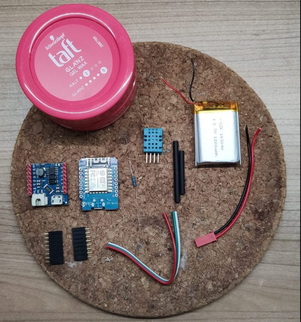
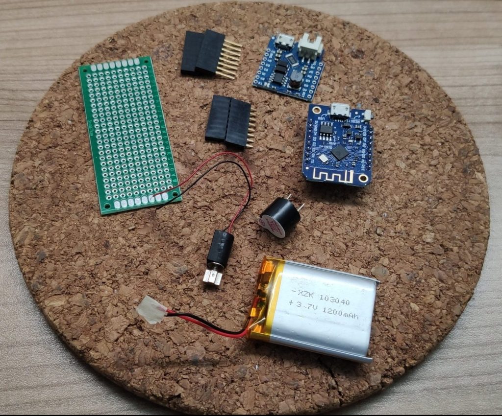
For this yard bell we will use the following components:
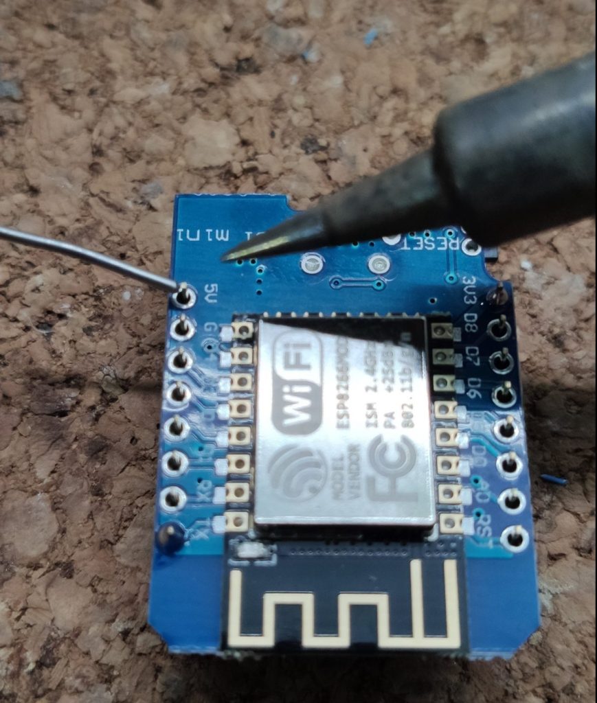
- A D1 Mini
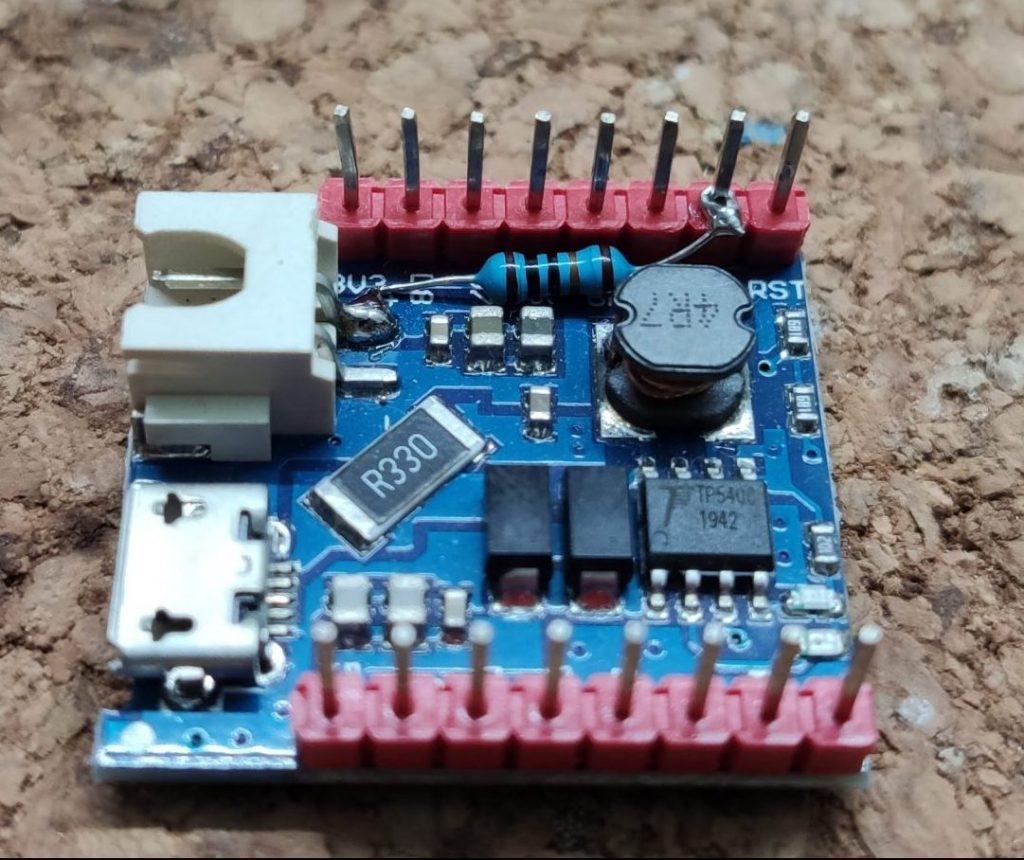
- A D1 Mini Battery shield
- Female pin headers long and short (mostly included with the D1 Mini)
- Male pins (mostly included with the D1 Mini)
- A 3V active Buzzer
- Some perfboard
- A 3V vibration motor
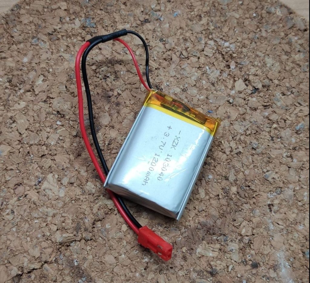
- A 3.7V Lipo battery
- A battery connector cable (optional, because you can solder the battery to the battery shield)
- A container / something similar as housing (I used a 3D printed project box from Evis Home)
- A trigger for the Home Assistant automation (I used a Zigbee button )
*Some links are affiliate links. If you use them to buy the parts for your project you will help me and my next project. These links will cause no extra fees or costs to you
Starting on a breadboard
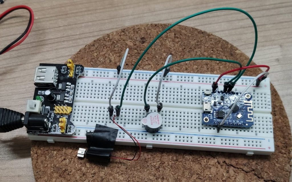
Because I had no clue if my idea would work, I started on a bread board. The D1 Mini is hooked up to 3.3V and the buzzer and the vibration motor are connected to two GPIO pins on the D1 Mini (D5 & D6). The idea is to pull both pins high when the Zigbee button is pressed which then turns on the buzzer and the vibration motor. After some delay both pins should turn low automatically. The D1 Mini is running ESPHome which makes it easy to announce both pins as momentary switches in Home Assistant.
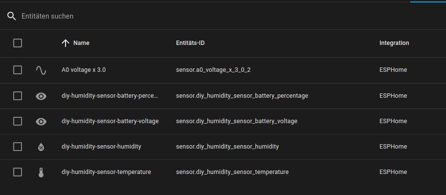
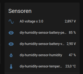
The ESPHome sketch and Home Assistant
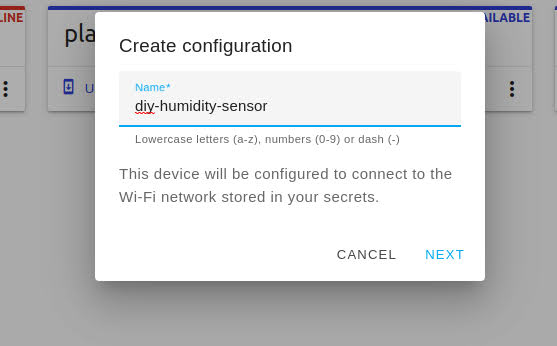
To make the pins available as momentary switches in Home Assistant I used the following sketch. This sketch connects to my Wifi and defines both pins as switches which auto turn off after 750-1000ms.
esphome:
name: diy-yardbell
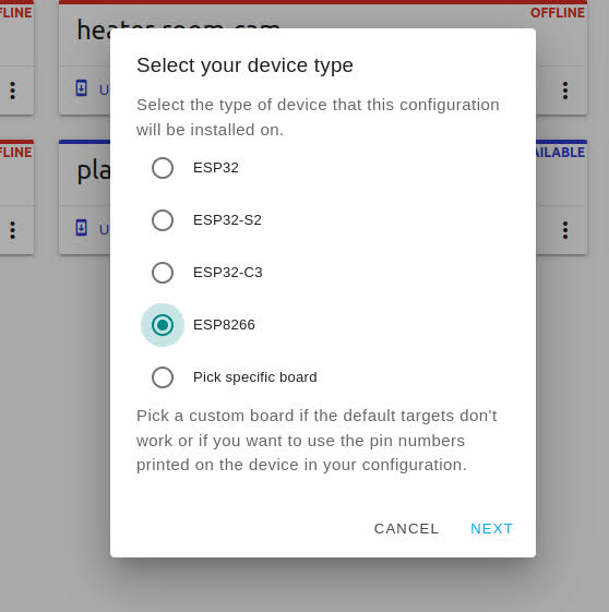
esp8266:
board: d1_mini
# Enable logging
logger:
# Enable Home Assistant API
api:
ota:
password: "SuperSecr3t"
wifi:
ssid: !secret wifi_ssid
password: !secret wifi_password
# Enable fallback hotspot (captive portal) in case wifi connection fails
ap:
ssid: "Diy-Yardbell Fallback Hotspot"
password: "SuperSecr3t"
captive_portal:
switch:
- platform: gpio
pin: D6
id: buzzer
name: "Buzzer"
icon: "mdi:volume-high"
on_turn_on:
- delay: 750ms
- switch.turn_off: buzzer
- platform: gpio
pin: D5
id: vibrator
name: "Vibrator"
icon: "mdi:vibrate"
on_turn_on:
- delay: 1000ms
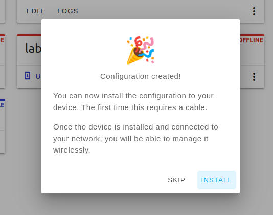
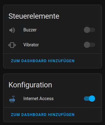
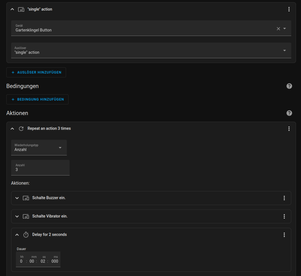
- switch.turn_off: vibratorAfter uploading this sketch to my D1 Mini, the two pins show up as buttons in Home Assistant and I was able to create an automation which triggers both switch 3 times in a row with a delay of two seconds.
With that all set I was able to give the project a first test.
Lets start soldering
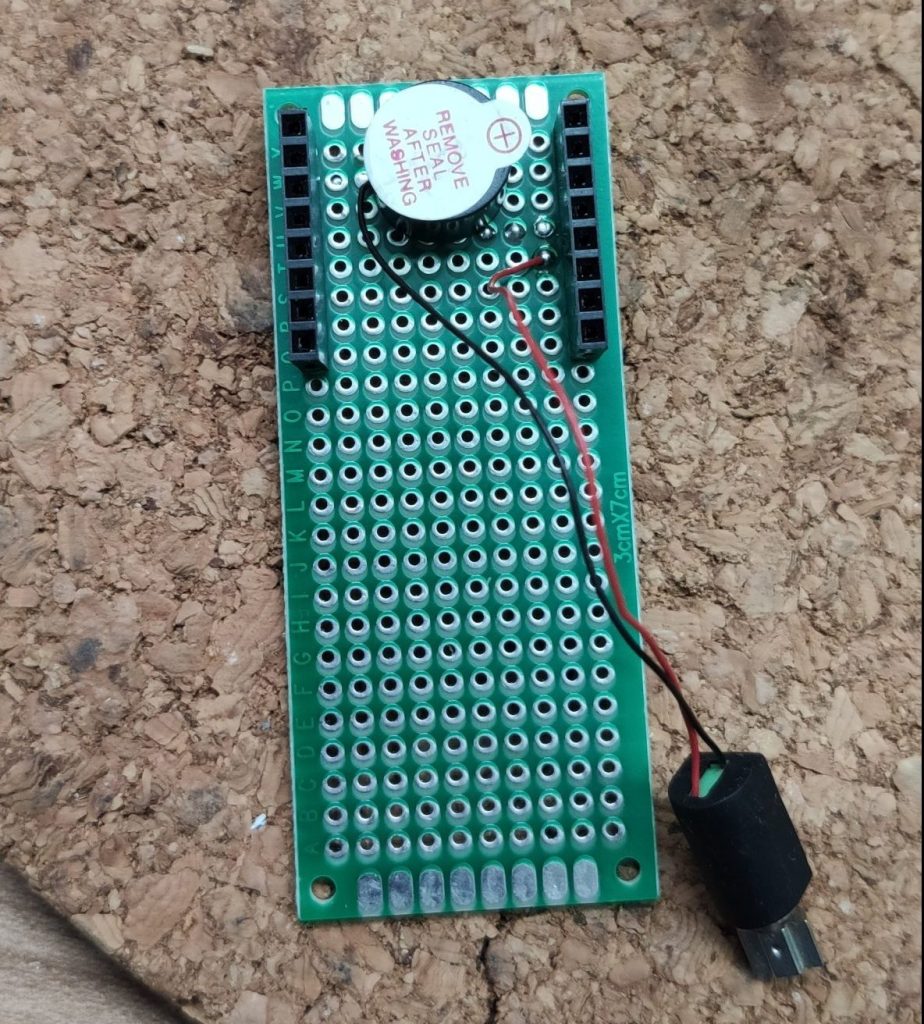
After the successful tests everything was ready to solder. I started with the short female connectors and soldered them onto the perfboard. Then I soldered the positive wire of the vibration motor to the D5 pin and the negative wire to the GND pin.
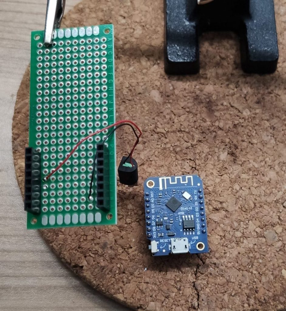
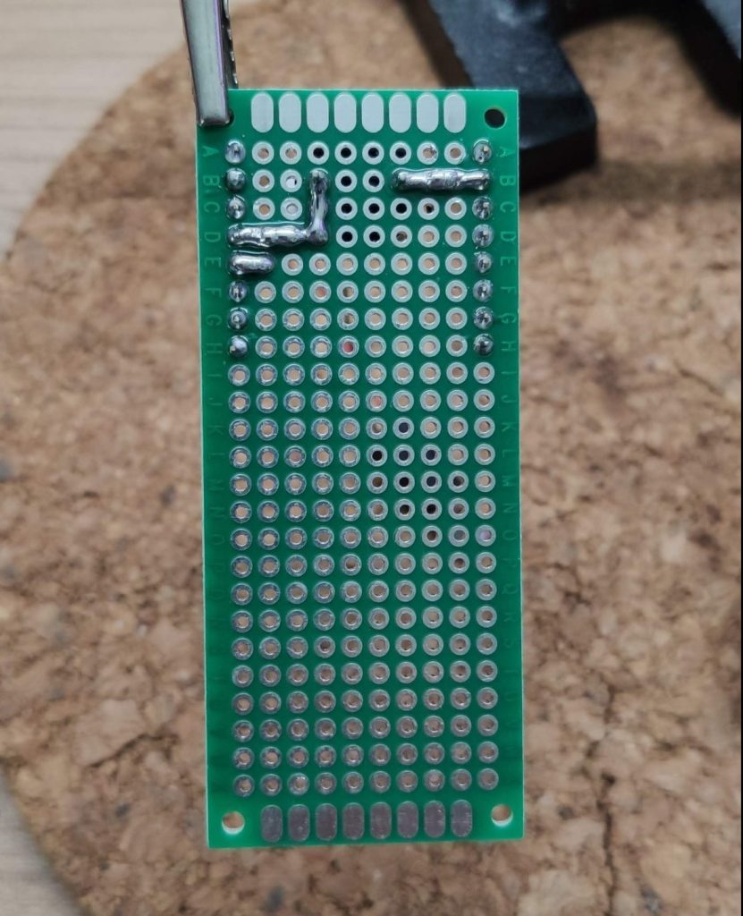
In the next step I soldered the buzzer onto the perfboard. I chose a position where the negative leg of the buzzer lines up with the negative wire of the vibration motor, for easier connection.
To persist the buzzer I soldered it in place and connected the positive leg to the D6 pin.
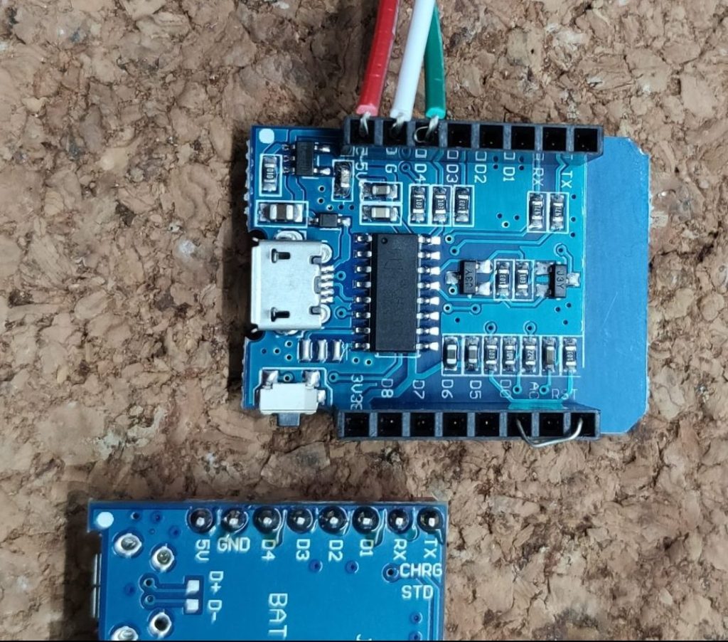
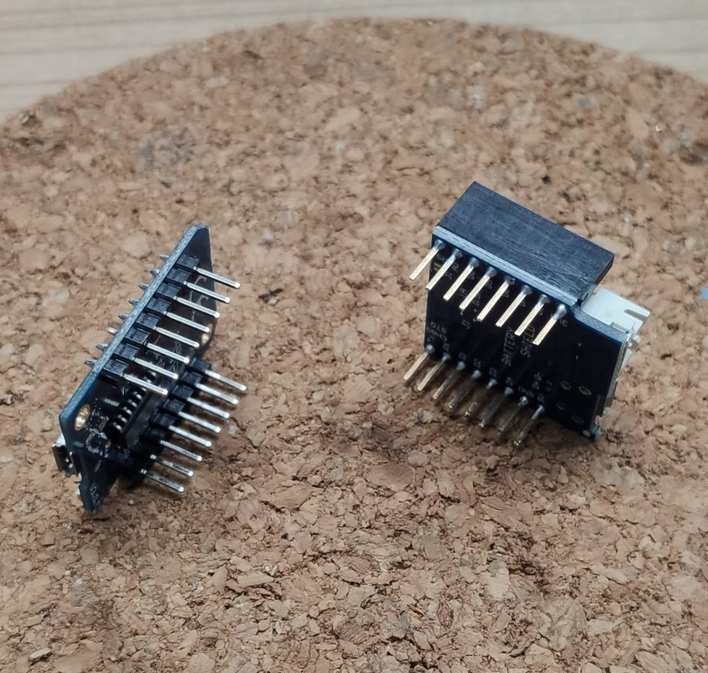
Last not least I soldered the long female pin headers to the D1 Mini battery shield and the male pin headers to the D1 Mini.
Stack it up!
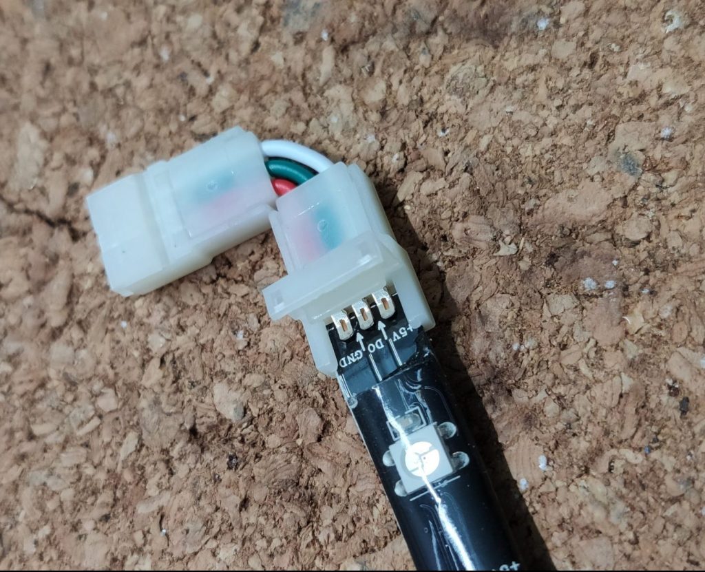
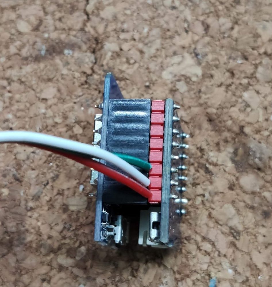
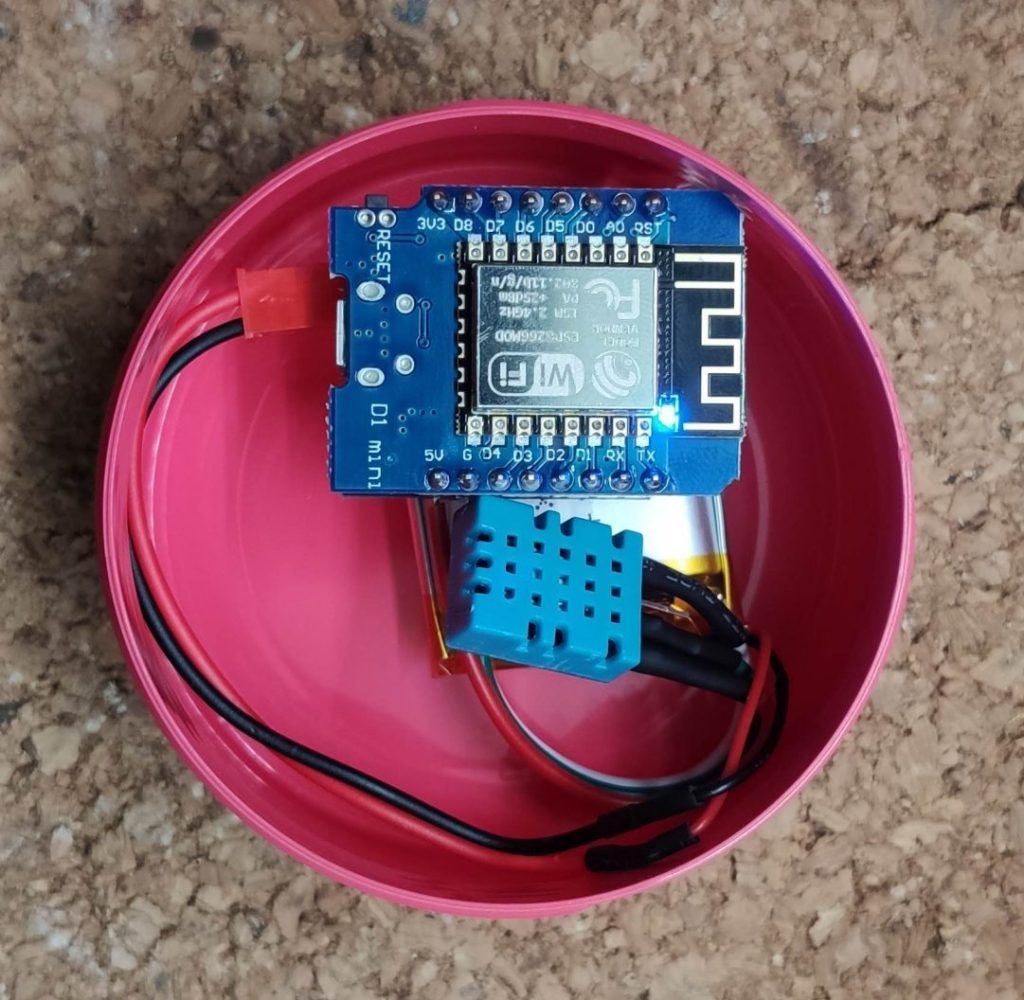
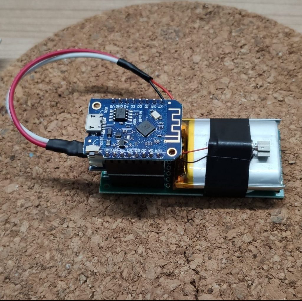
With the complete soldering I was able to stack everything together. I stacked the battery shield on top of the perfboard that the pins were lined up and placed the battery next to it. Then I realized that my battery wires were a bit to short so I had to extend them a few cm’s. The vibration motor went on top of the battery to keep the form factor small.
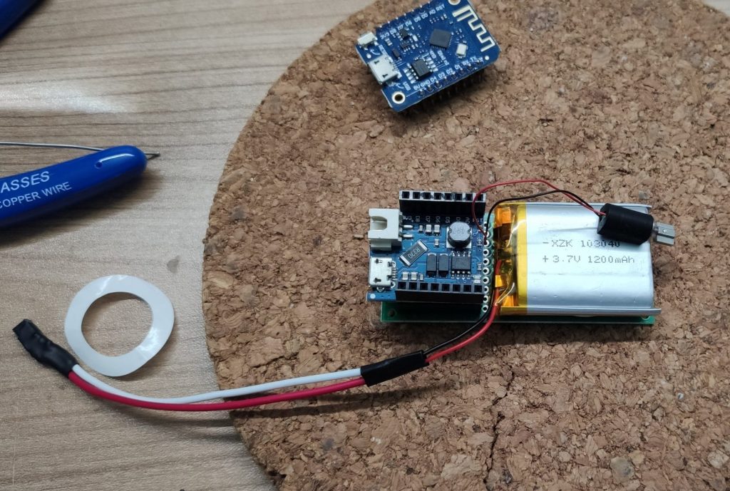
To finish the assembly I stacked the D1 Mini on top, connected the battery to the battery shield and secured the vibration motor with some electrical tape.
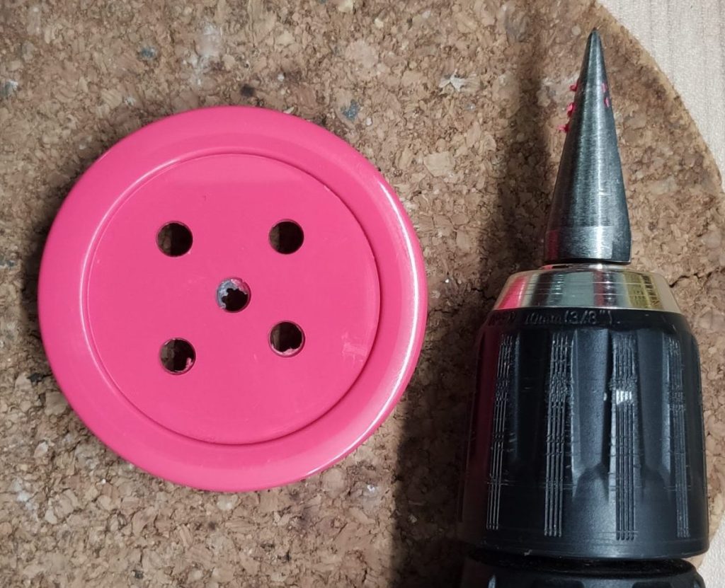
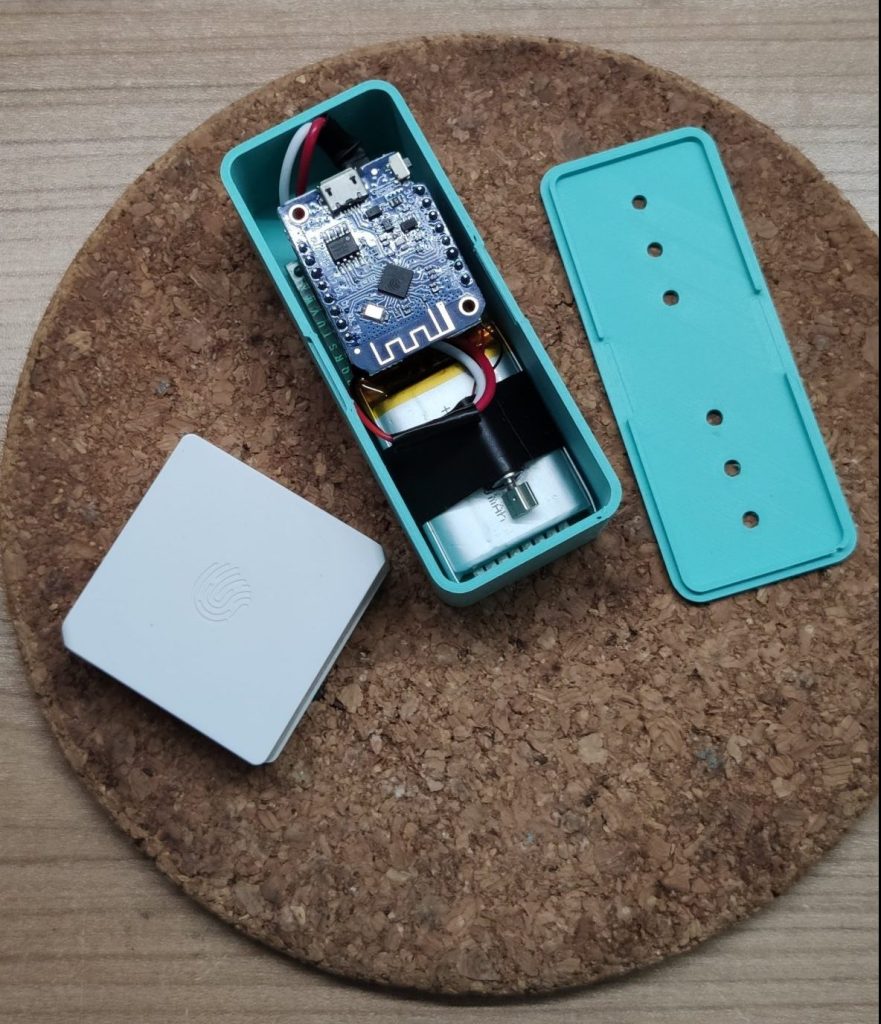
The enclosure
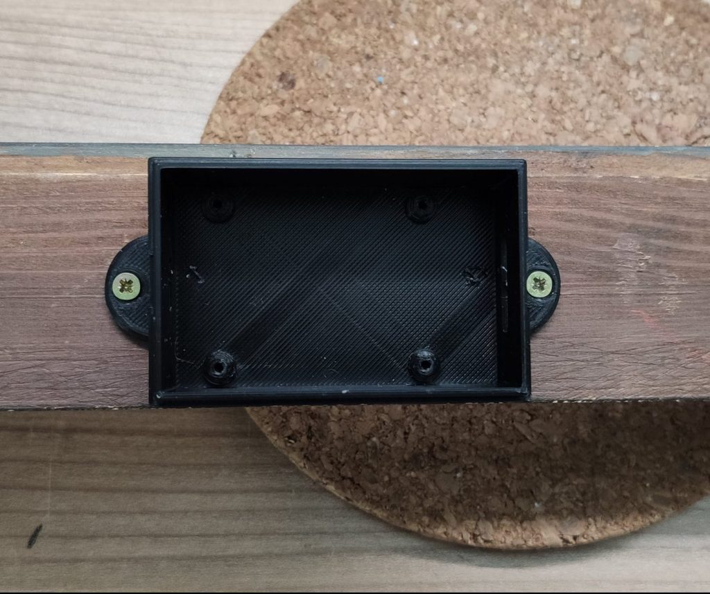
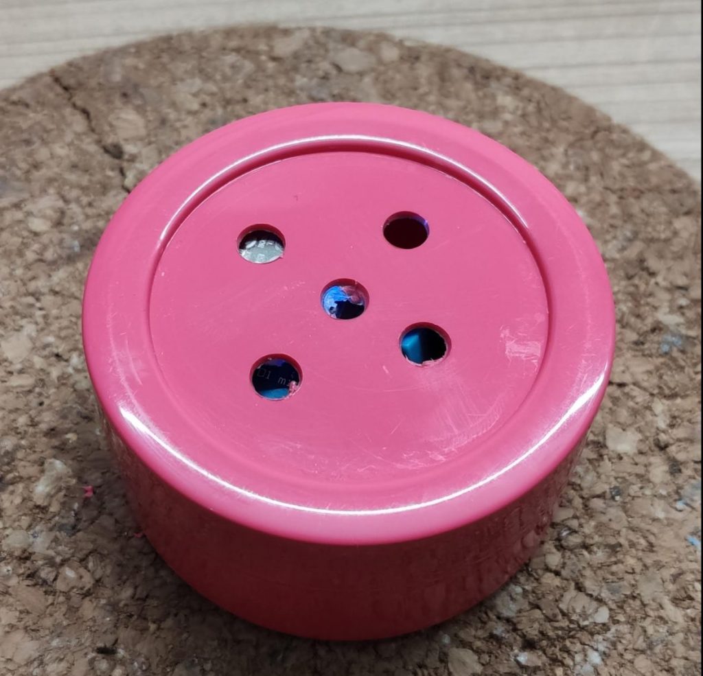
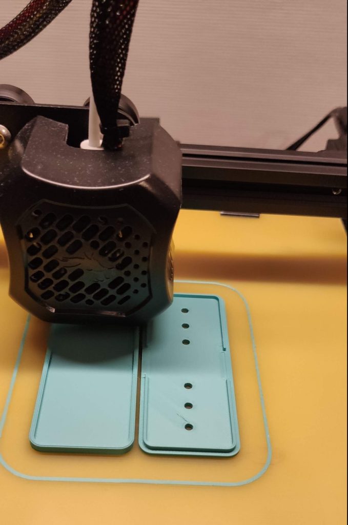
As a reaction on my testing tweet I got an DM from Evis Home who asked me If I want to try his tinkercad code block for a project box. This was an awesome coincidence, because I simply had to measure the dimension of the perfboard stack, typed that into his script and within seconds the model was ready. I only had to import the lid into tinkercad to add some holes so that the sound of the buzzer was easier to hear.
The final yard bell project
After the print was finished I put the perfboard stack into it. It fit’s perfect 🤩. That was the time to test everything for the last time.
Sum up
After some months of project break, this was a really fun and also useful one 🤓. I really like how simple such ideas can be realized with ESPHome and Home Assistant. With only a few components I could built a DIY yard bell which is much more flexible than a off the shelf product. E.g. you could replace the Zigbee button with a motion sensor or activate the yard bell only in the evening. It’s also possible to replace the buzzer with a sound module that plays you favorite song. The possibilities are up to you 😁 .
As always, if you like this project feel free to ping me on twitter and share pictures of your own build.