๐Ÿ”ฆ๐Ÿ‘ง๐Ÿง’DIY marmalade lamp you can build with your kids

Couple months ago my kids ask me to build something with them. So I started to think about a small project that is simple and teach them something about electricity and tinkering. I ended up with a rechargeable lamp based on a marmalade jar. As I posted the results on twitter I got some feedback and PM’s on how we built it and what components were used. This article is a complete walk trough of this project including an updated component list.

Marmalade lamp

Parts list

For this project we will use the following components

*Some links are affiliate links. If you use them to buy the parts for your project you will help me and my next project. These links will cause no extra fee or costs to you

All components

Time to teach the kids how to solder

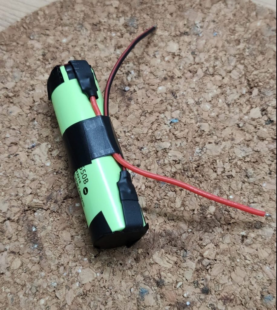
Lets start with the battery. I use 3400mAh Li-ion battery with a voltage of 3.7V. This fits perfect to the charging unit and also lights up the cheap led strip pretty well. This battery comes with already soldered metal tabs, which makes wire soldering much easier. Take some wire and solder it to tabs. Keep an eye on the polarity and the cable colors. Is used red for positive / VCC and black for negative / GND.

Soldered wired on the tab

Next, secure the connections and the sides of the battery with electrical tape to prevent shorts.

Finished battery

Now grab the charging unit and presolder the pads on non USB-C side. The inner pads are for the battery the outer pads are for the load / the led strip in our case.

Presolder the battery and load pads

After presoldering the pad grab the battery and solder the wires to the inner pads. Double check the polarity and the markings on the board. The positive side is marked with B+ and the negative with B-

Connected charging unit

You can now test the charging unit by hooking up an USB-C cable. If it’s in charging mode you will see a red led light up. The battery is fully charged if the blue led will light up. In case you see both leds come up and one of them starts to flicker heavy, you might have a problem with you connection to the battery.

Charging process

Bring up the lights

Before we connect the charging unit to the led strip we have to prepare the wires and the jar lid. First drill a hole into the lid of the jar where the button fits in. I used a conical metal drill bit to find out the perfect size, but any large metal drill should work.

Ready to drill

Now take a piece of wire and separate the black and the read wire. Then cut the red in half and presolder all ends.

Prepared wires

After that solder the to read cables to the button and put it into the lid of the jar. To secure the soldering joints and preventing shorts apply some small heat shrink to the button.

Lid with button

Grab now the led strip and the black wire and solder it onto the negative pad on the led strip. Take then the jar lid and solder one red cables to the positive pad on the led strip. As well as on the button secure the soldering joint with a heat shrink

Led strip connected to the button in the lid

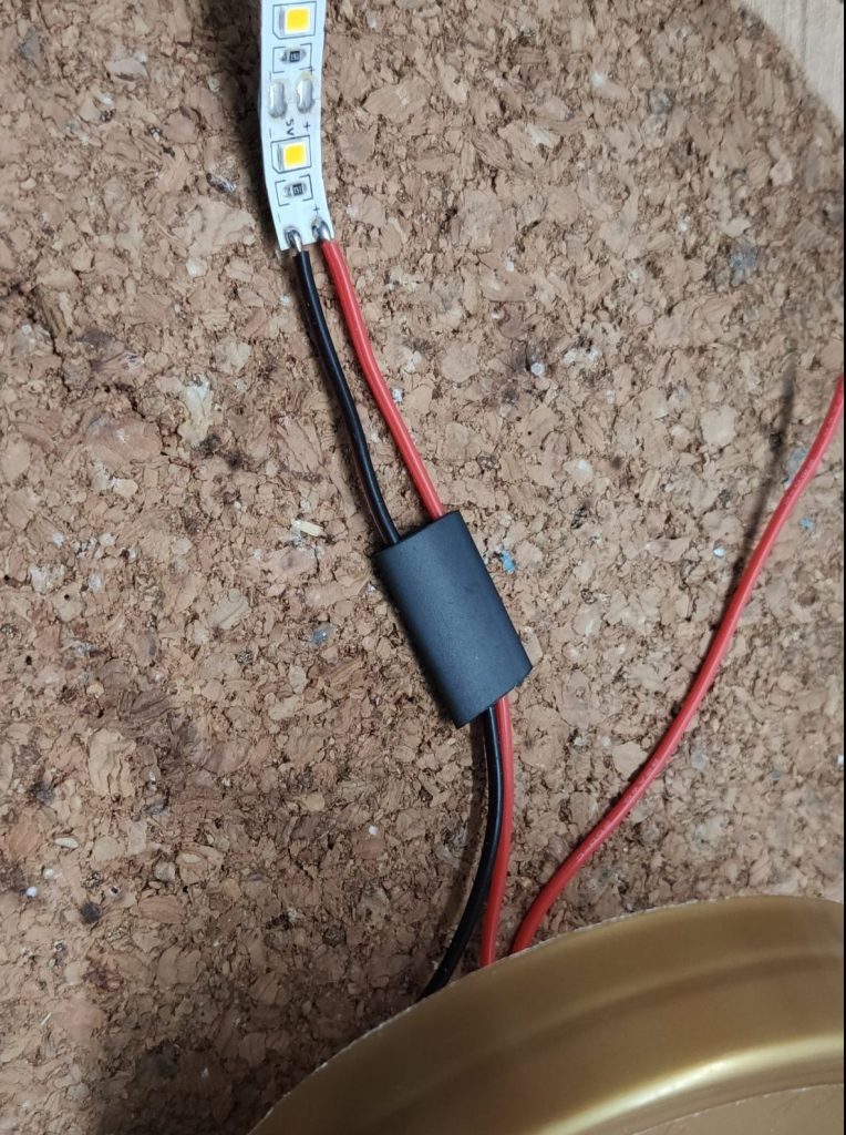
The two wires left over can now be soldered to load pads of the charging unit. Simply red to red and black to black. That completes the circuit and the marmalade lamp is ready for a first bench test. So press the button in the lid and the led strip should light up. If you want, you can wrap the charging unit in some kapton or electrical tape for more security.

Bench test

Last not least, put everything into the jar, screw on the lid and you’re done ๐Ÿฅณ.

Final reslut

Some Mesurements

To teach the kids more about current you can calculate approx the life time and the charing time of the by measuring the current which is use by the led strip and which is provided from the charging unit during the charging process.

Current used from the strip

With a usage of 166mA on 3400mAh battery the strip should light about ~20h. The charging unit provides about 630mA. This results in a charging time of round about ~5h.

Charging current

Sum up

That was fun! Hope you enjoyed this project as much as me and my kids did. You could modify this project a bit to make it more secure for younger children, e.g. you could replace the marmalade jar with transparent plastic box from the dollar store. You can also let the kids more customize it. e.g. they could glue some colored transparent paper or sticker on it.

If you like this project, feel free to share the article or an image of the DIY marmalade lamp you built ๐Ÿ˜‰

๐ŸŽ„ Xmas tree moisture sensor ๐ŸŽ„

This little Xmas tree moisture sensor is a perfect give away for family and friends. I soldered about 10 of them this year to give them away and the feedback was just awesome. This little helper prevents your Xmas tree to dry out and loose pine needles early. This usage is quite easy, hang the ball into your Xmas tree and place the two electrodes into the water reservoir. If the reservoir is filled, the led is off, if it’s on, the reservoir is empty and you have to water your tree.

Xmas tree moisture sensor

Parts list

For this project we will use the following components

  • A transparent Xmas ball
  • A 2N2222 NPN transistor
  • A 220 Ohm resistor
  • A CR2032 battery holder + battery
  • A red led
  • About 2m of 26 AWG wire (2x 1m)
  • Wire ferrules
  • Hot glue
All components

Solder it up

Bend the legs of the transistor and the led, then solder the collector of the transistor to the cathode (short leg) of the led. Because the transistor has no markings for the pins ensure that flat side of the transistor faces downside. In this orientation the pinout is, (f.l.t.r) collector, base, emitter.

Led and transistor soldered together

Now take the CR2032 battery holder and flip it and solder the led transistor package to. Keep an eye on the polarity, the led must be soldered to the positive side of the batter holder.

Tipp: Pre solder the legs and the pins on the battery holder.

Soldered battery holder

In the next step we will solder the risitor between the anode of the led and the base of the transistor. This will ensure that we have matching current on the base if the circuit is closed.

Resistor between anode and base

With the resistor in place, the circuit is complete and we can now have a look at the wires. So grab the wires and pre solder the two ends. This way it becomes much easier to solder the wire to board later.

Presoldered wires

After that solder the wires to the base and the emitter of the transistor and cover the everything with hot glue.

Wires soldered and ready for hot glue

Prepare the Xmas ball

Until the hot glue gets cold, we can focus on the transparent Xmas ball. To get the wires through we have to drill a hole inside the ball. I use a 5mm metal drill and place the hole about 2cm away from the edge of the half ball. If you drill the hole more to the edge it might crack the plastic.

Ready to drill

Now take the ends of the wires and put them through the drilled hole. Then grab the ferrules and applie them to the end of the wires. Don’t add the ferrules first, because then they wont fit trough the hole.

Cables with ferrules on it

Last not least, put add a CR2032 battery into the battery holder and add both halfs of the ball together. The led should light up beacuse there is no contact between the probes.

Probes with no contact

Now, hold the probes into water. The led should turn off because the contact is closed.

Probes with water contact

Tipp: To hold the probes of the Xmas tree moisture sensor near to each other, you could use an insulating screw joint.

Sum up

And that’s it. You have successfully build your own Xmas tree moisture sensor ๐Ÿ˜ƒ So, start over again and build some more of these guys for sharing them with your family and friends.

If you like this project, feel free to share the article or an image of your Xmas ball ๐Ÿ˜‰

๐Ÿƒ๐ŸŒก๏ธ๐Ÿ’ฆ DIY Multi sensor with tasmota

In this project we’ll build a DIY Multi sensor which can recognize motion and measures the current temperature / humidity in the room. The brain of the sensor will be a D1 Mini (esp8266) which uses the tasmota firmware to collect all the data, hooks into your local WIFI and send them to Home Assistant.

The DIY Multi sensor

Parts list

In this project we will use the following components

  • One D1 Mini (esp8266) incl. long pins
  • An DTH11 temperature / humidity sensor
  • A AM312 PIR sensor
  • A 3D printed enclosure from thingiverse
  • Couple 0.8mm wire
  • Some heatshrinks
  • Hot glue
All components

Wiring up the components

First of we will solder the long pins to the D1 Mini. I chose the long variants because both sensors will use 5V and GND from the same pins. Using long pins makes the wire soldering easier later on. Alternatively you could crimp your own dual dupont cable to power both sensors, but i.m.h.o soldering works much better for a solid connection.

Solder the long pins

Second, we’ll solder the wires to the sensors. I my case, I used black for GND, red for 5V/VCC and yellow as the data wire. Double check the pins on the sensors, e.g. mixing GND and VCC will destroy them immediately. The AM312 should have markings on the board to identify the pins. The DTH 11 doesn’t so check the sensor description or take a look at my pinout on the picture.

Soldered sensors

After preparing the sensors we’ll solder them to the D1 Mini. Watch out that the wires of AM312 must be run to the enclosure first, because the sensor is mounted outside in not inside out.

Sensor outside in

We will solder the wires as follows to the D1 Mini:

  • Both sensor 5V / VCC to the 5V pin
  • Both sensor GND to the GND pin
  • The data wire of the AM312 goes to pin D1 (GPIO05)
  • The data wire of the DTH11 goes to pin D2 (GPIO04)

Also ensure to add a couple heatshrinks and some hotglue to prevent a short circuit inside the enclosure.

Sensors soldered to the D1 Mini

Last not least we will place all components into the enclosure, add a drop of glue to hold the AM312 in place and hook up a micro USB cable to connect everything to our PC.

Sensors in the enclosure

Installing Tasmota

After finishing the wiring we’re now able to flash the Tasmota firmware on the D1 Mini to connect it with Home Assistant and your MQTT broker.

First, plug in your multi sensor using a USB cable with data wires in it, open the Chrome/Chromium Browser, go to the Tasmota installation page and simply click “connect”

Tasmota installation wizard

Second, select the USB port your device is connected to and click “connect”. If your device does not show up you might need to install an additional driver. If so please try to install the CP210x or the CH341 drivers and retry the step.

Select device

After that go to the wizard, wait until Tasmota is installed on the D1 Mini. If the installation finishes successfully, your D1 Mini will spawn a WiFi-Access point called Tasmota_XXX.

Installation in progress

Connect to the access point and go to the IP 192.168.4.1. Enter your WiFi credentials to add your multi sensor to your home network. Please keep in mind, that only 2.4GHz networks are supported.

Connect it to your home network

Configuring Tasmota

If the device is connected its time to configure the multi sensor the way we want it. Open the IP address in your browser and configure the device as follows:

1. Click on “Configuration” => “Configure Other”

  • Enable MQTT and the HTTP API
  • Give your device a proper name
  • Click save
Other settings

2. Click on “Configuration” => “Configure MQTT”

  • Add your MQTT IP and credentials
  • Change the topic to something more useful
  • Click save
MQTT settings

3. Click on “Configuration” => “Configure Module”

  • Select the module type generic
  • Click save
  • Click again on “Configuration” => “Configure Module”
  • Select “Switch” on the entry D1 with the number 1
  • Select “DTH11” on the entry D2
  • Click save
Module settings

You should now see the first temperature and humidity data on the Tasmota home screen.

Temperature values on home screen

To bring the AM312 in our DIY Multi sensor to life we have to add some console command to Tasmota. At the moment the PIR Sensor will only trigger the POWER event in the console. With the following commands we will configure it to send a useful MQTT payload which we can use in Home Assistant automation.

To set these configuration go to the home screen of your Tasmota device and click on “Console”. Than post the following commands one by one into the console and press “Enter”.

SwitchMode1 1
SwitchTopic 0
Rule1 on Switch1#state=1 do publish stat/%topic%/PIR1 ON endon on Switch1#state=0 do Publish stat/%topic%/PIR1 OFF endon
Rule1 1

In a nutshell, these commands will create a rule which will send the “ON” payload to the /stat MQTT topic if motion is detected and “OFF” if the sensor returns to the normal state. If you want to learn more about the SwitchMode, SwitchTopic and the Rule command please checkout the Tasmota Button and Rule documentation.

You can verify the result of the rule in the Tasmota console or on directly on your MQTT broker.

Console output

Use the data in Home Assistant

To use all the data in Home Assistant we can simply use the regular Tasmota and the MQTT integration. The Tasmota integration will create the entities for the DTH11 sensor and for the AM312 sensor we can simply watch for the MQTT topic and payload we created earlier in our automation.

Home Assistant Tasmota integration

If you want to use the the MQTT Result in Lovelace, you can create a new binary sensor for this in your configuration.yaml. This sensor can be used with the entity card and looks way better on a dashboard.

mqtt:
    binary_sensor:
      - unique_id: binary_sensor.tasmota_multisensor_2_pir_sensor
        name: "tasmota-multisensor-2 PIR Sensor"
        state_topic: "stat/tasmota_multisensor_2/PIR1"
        availability_topic: "tele/tasmota_multisensor_2/LWT"
        qos: 1
        payload_available: "Online"
        payload_not_available: "Offline"
        device_class: motion

Sum up

And you’re done ๐Ÿ˜…. I hope you enjoyed the build process as much as I did and that you’re now looking at your own functional version of the DIY Multi sensor.

If you like, feel free to share your sensor on twitter and link me ๐Ÿ˜‰